Micro-fluidic chip and application thereof

A microfluidic chip and microvalve technology, applied in laboratory containers, enzymology/microbiology devices, microbial measurement/inspection, etc., can solve problems such as experiment failure, amplification pollution, cell loss, etc.

Active Publication Date: 2021-07-06
BEIJING INSTITUTE OF TECHNOLOGYGY
View PDF8 Cites 5 Cited by
  • Summary
  • Abstract
  • Description
  • Claims
  • Application Information

AI Technical Summary

Problems solved by technology

However, the existing microfluidic chip has a single function and can only complete one step in antibody detection and gene amplification.
The transfer of a small amount of cells between different chips is likely to cause cell loss and amplification contamination, leading to the failure of the experiment

Method used


Image

  • Micro-fluidic chip and application thereof
  • Micro-fluidic chip and application thereof
  • Micro-fluidic chip and application thereof

Examples


Embodiment 1

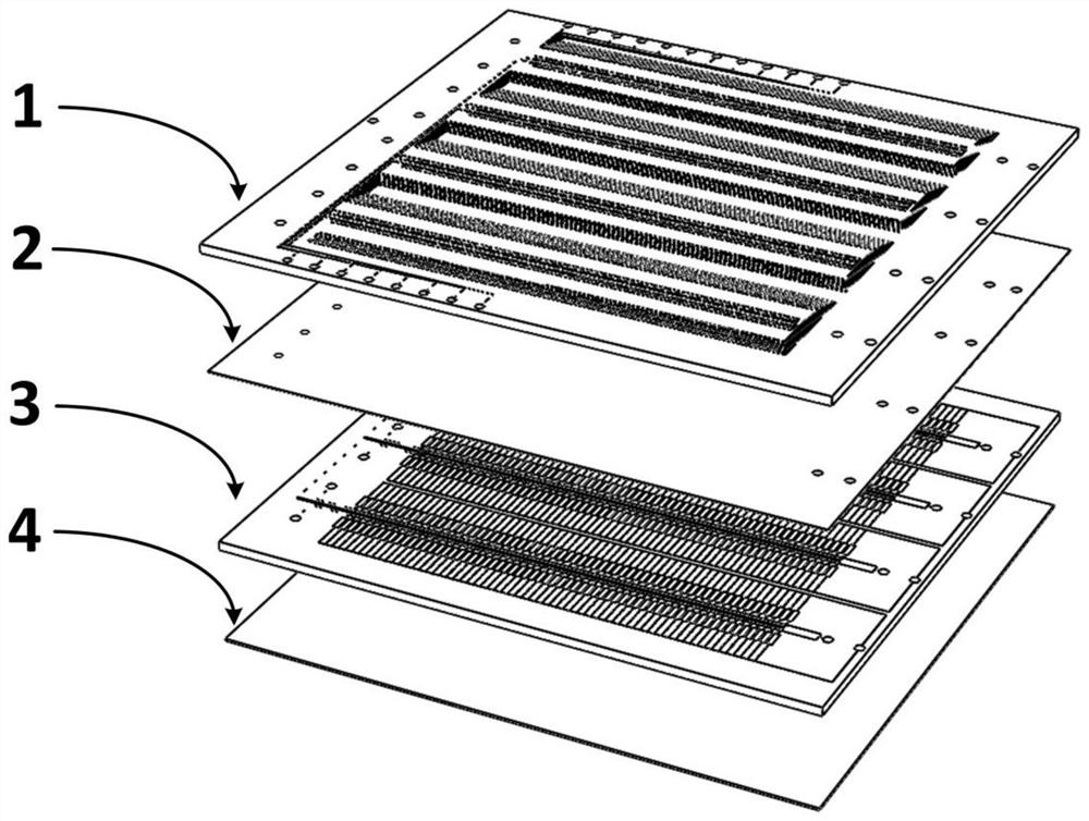
[0073] This embodiment provides a microfluidic chip, which is composed of a four-layer structure stacked together and sealed to each other. The four-layer structure is respectively a microvalve control layer 1, a microvalve film layer 2, The cell treatment layer 3 and the base layer 4 (made of glass); the microvalve control layer 1, the cell treatment layer 3 and the base layer 4 are transparent structures. The microvalve control layer 1, the microvalve film layer 2, and the cell treatment layer 3 are all made of PDMS material, and oxygen plasma is used to assist bonding. In other implementation methods, the microvalve control layer, the microvalve film layer, and the cell treatment layer can be Layer material to choose the appropriate sealing method.

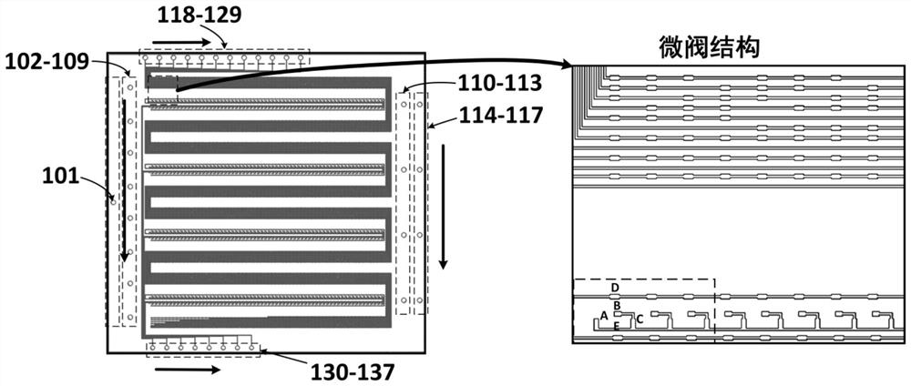
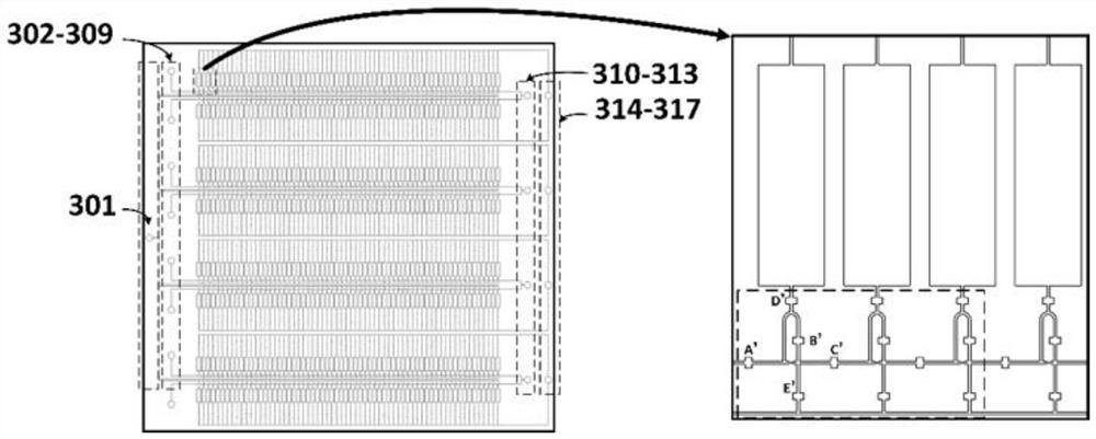
[0074] For a schematic diagram of the expansion of each layer of the microfluidic chip, see figure 1 . The schematic diagram of the top view of the microvalve control layer is shown in figure 2 In the left figure in the fig...

Embodiment 2

[0121] This example provides an application method for screening hybridoma cells and antibody gene amplification using the above-mentioned microfluidic chip. Specifically, the specific application method is described as follows by taking hybridoma cells targeting CD45 protein as an example:

[0122] All reagents are prepared in nuclease-free water during operation, and consumables are nuclease-free.

[0123] All the experimental steps are carried out in the cell room in a sterile environment, the consumables and instruments are sterilized in advance, and the reagents are all sterile.

[0124] 1. To pretreat the microfluidic chip, inject 75% ethanol into the microfluidic chip from the liquid injection port for 5 minutes to sterilize and infiltrate the surface of the flow channel to increase hydrophilicity. Inject sterile phosphate-buffered solution (PBS) to wash the ethanol in the channel. Close each chamber and enter the gene amplification chamber control microvalve D on the ...


PUM

PropertyMeasurementUnit
thicknessaaaaaaaaaa
thicknessaaaaaaaaaa
sizeaaaaaaaaaa

Abstract

The invention relates to the technical field of detection and amplification of unicellular antibodies, specifically to a micro-fluidic chip and application thereof. The chip consists of a micro-valve control layer, a micro-valve thin film layer, a cell treatment layer and a substrate layer which are sequentially stacked together and are mutually sealed; the chip has a liquid injection port, a cell suspension inlet, a cell suspension outlet, an amplification product collection outlet, a micro-valve air inlet, a micro-valve air inlet, an amplification product release micro-valve control structure and a liquid flow micro-valve control structure; the amplification product release micro-valve control structure controls release of amplification products through a micro-valve on a gas flow channel; the liquid flow micro-valve control structure controls the flow of liquid in the cell treatment layer through the micro-valve on the gas flow channel; the cell treatment structure comprises a plurality of cell treatment units; each cell treatment unit comprises a liquid flow channel and a gene amplification chamber; and capture, identification and amplification of cells are accomplished in the cell treatment units. According to the invention, all the functions are integrated on the same chip, and operation is quick, simple and convenient.

Description

technical field [0001] The invention relates to the technical field of single cell antibody detection and amplification. Specifically, it relates to a microfluidic chip and its application. Background technique [0002] Monoclonal antibodies have become one of the effective methods for tumor treatment, virus resistance and disease diagnosis, especially in the field of immunotherapy. Antibody molecules are composed of 2 identical heavy chains and 2 identical light chains, and the same chains and different chains are connected by disulfide bonds to form a Y-shaped structure. The N-terminal 110 amino acids of the heavy and light chains are highly variable, known as variable regions, which have the function of specifically binding to antigens. Therefore, obtaining the gene sequence of antibody variable regions is a key step in antibody development. [0003] Antibody development platforms include hybridoma technology, phage display technology and single B cell technology. Hybr...

Claims


Application Information

Patent Timeline
Patent Type & Authority Applications(China)
IPC IPC(8): B01L3/00C12M1/34C12M1/00G01N33/569G01N33/58C12Q1/686
CPCB01L3/5027G01N33/56966G01N33/582C12Q1/686B01L7/52C12Q2565/629
Inventor 李勤魏泽文张卫凯
Owner BEIJING INSTITUTE OF TECHNOLOGYGY
Why Eureka
Try Eureka