Direct heat supply type multi-stage series-parallel turbulent bed pyrolysis stripping furnace in combustion flame furnace

A flame furnace and turbulent bed technology, applied in the field of pyrolysis and stripping reactors, can solve the problems of slow pyrolysis reaction speed, large difference in treatment effect, low heat utilization efficiency, etc., to improve pyrolysis reaction and stripping The effect of reaction speed, improvement of organic matter conversion and recovery yield, improvement of heat supply efficiency and heat absorption efficiency

Pending Publication Date: 2021-07-09
NINGBO LIANTONG EQUIP MFG
View PDF0 Cites 0 Cited by
  • Summary
  • Abstract
  • Description
  • Claims
  • Application Information

AI Technical Summary

Problems solved by technology

[0007] The pyrolysis method varies greatly depending on the pyrolysis reactor (pyrolysis furnace) technology. The "batch" pyrolysis furnace can feed materials once and discharge slag once, so it cannot be continuously produced, and the processing scale of the pyrolysis furnace is small; " The continuous type pyrolysis furnace has a small processing scale, and the continuous operability is not high due to various factors. At present, both "intermittent" and "continuous" pyrolysis furnaces use organic solid waste in the furnace, heat carrier (External heat supply) Outside the furnace, the "indirect" heat supply and pyrolysis method in which the organic solid waste in the jacket is in direct contact with the heat has low heat transfer efficiency and low heat absorption efficiency, resulting in low heat utilization efficiency and heat loss. Problems such as slow decomposition reaction speed, long reaction time, high energy consumption, pyrolysis solid residues cannot meet the requirements of ultra-clean emission environmental protection indicators, etc.

Method used


Image

  • Direct heat supply type multi-stage series-parallel turbulent bed pyrolysis stripping furnace in combustion flame furnace
  • Direct heat supply type multi-stage series-parallel turbulent bed pyrolysis stripping furnace in combustion flame furnace
  • Direct heat supply type multi-stage series-parallel turbulent bed pyrolysis stripping furnace in combustion flame furnace

Examples


Embodiment 1

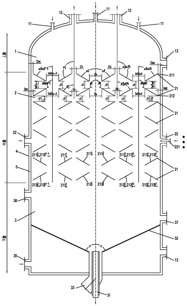
[0073] The implementation principle of Example 1 is: fuel and air or oxygen air or oxygen enter the lower furnace 3, the combustion reaction produces a high temperature flue gas, and is pressed against the lower furnace 3 pressure gas inlet 35 and The pressure-insulating gas in which the pressure gas gas and / or the outer passage of the fuel burner 31 is allocated by the gas distributor 32, and the upper pressure gas inlet 37 enters the upper pressure gas inlet 37 enters the heat transfer to heat After the temperature required to decompose the reaction, the upper entry into the bottom of the middle furnace 2, and the pyrolysis transfusion reaction of the pairwriting microspactic bed 22 in which the n-stage is connected is supplied to the heat.

[0074] Solid waste material (organic solid waste) containing organic solid waste materials from the upper furnace 1 enters the upper furnace 1 in gravity downward, with a mixture of upstream high temperature flue gas and pyrolysis-disodin...

Embodiment 2

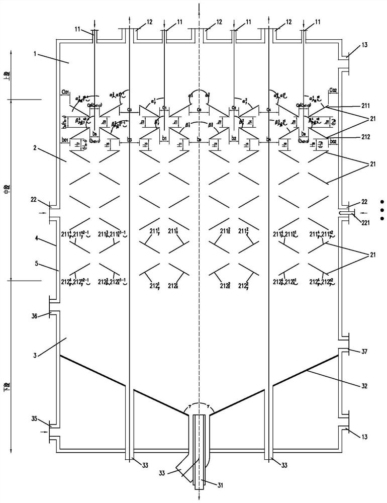
[0080] A combustion flame furnace directly gives a heat-free multi-stage string pairwriting bed thermal solution furnace, see figure 2 The furnace housing 4 including a vertical square structure includes a cross-sectional shape of the upper stage furnace 1, the mid-stage furnace 2 and the lower furnace 3, the upper furnace 1, the mid-stage furnace 2, and the lower furnace 3, and the upper section The furnace housing 4 cross section is 4500mm in the case of 4500mm, and the height of the straight-section is 2000mm. The thickness of the refractory thermal lining is 150 mm; the outer furnace housing 4 inner diameter length X width is 4500 x 3500 mmmm, and the straight height is 20840mm. The refractory thermal lining 5 thickness is 250 mm; the cutting furnace 3 of the lower furnace 3 is 4500mm, and the height of 4000 mm is 4000 mm, and the refractory thermal lining 5 has a thickness of 300 mm. The interval of the pyrolysis of the reaction pressure is from -0.05 mPaG-0.1 MPAG, and the t...

Embodiment 3

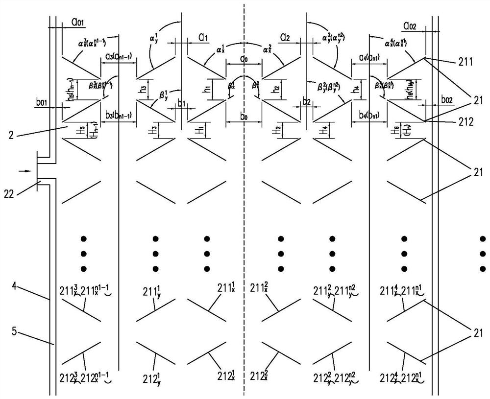
[0087] The present embodiment differs from the first embodiment in that the pairwriting microspactic bed setting is different, specifically, see image 3 with Figure 4 Mid-stage furnace 2 sets 24 sets of parallelized microspactic bed 21. Each set of turbulent suspension micro-reactive beds 21 is composed of a group composite upper conductive plate 211 and a group composite lower conductive plate 212, and a central axis symmetrical arrangement in the center of the furnace housing 4; each group of composite Topped guide plate 211 is two rectangles (211x1, 211x2, 211x3, 211x1, 211x2, 211 x 3, 211x1, 211x2, 211x3, 211x4) and 2 upper guides (5) (5) The inner wall portion is a circular arc. The structural shape symmetry is interleaved in parallel, wherein 211x1 and 211x2 are central axis symmetrical in the centerline of the center line of the furnace housing 4, and there is a venting hole of 850 diameters 5 mm. The 211Y1 and 211Y2 are central axis symmetrical in the center of the cavity ...


PUM


Abstract

The invention relates to the field of pyrolysis stripping reactors, in particular to a direct heat supply type multi-stage series-parallel turbulent bed pyrolysis stripping furnace in a combustion flame furnace. The direct heat supply type multi-stage series-parallel turbulent bed pyrolysis stripping furnace comprises a furnace shell, and the furnace shell comprises an upper section furnace, a middle section furnace and a lower section furnace which communicate with one another; the upper section furnace is provided with an organic solid waste inlet and a gaseous mixture outlet; the middle section furnace is provided with a plurality of serially-connected groups of parallel turbulent micro-reaction beds; the lower section furnace is provided with a fuel burner, a pressure-temperature gas inlet and a residue outlet; and fuel is combusted through a fuel combustor to generate high-temperature flue gas which flows from bottom to top and is in direct contact with organic solid waste to provide heat. The direct heat supply type multi-stage series-parallel turbulent bed pyrolysis stripping furnace has the effects of improving the heat supply efficiency and the heat absorption efficiency of the organic solid waste pyrolysis stripping process and reducing the energy consumption.

Description

Technical field [0001] The present application relates to the field of pyrolysis of the transfusion reactor, in particular, involving a combustion flame furnace direct to the heat-dissipating multi-stage parallel jamping machine heat dissipating furnace. Background technique [0002] With the acceleration of my country's economic development and urbanization process, the resource consumption is increasing, and the output of various waste production, diversified waste form, soil and groundwater pollution, etc. are more severe. The national environmental protection regulations require reduction and harmless governance to environmental emissions, and use appropriate technology to achieve resource recycling requirements for environmental emissions requirements. Using, contaminated soil needs to repair the governance to achieve agricultural or urbanized commercial soil requirements. [0003] These organic solid waste materials (organic solid waste) have three major categories. First, ...

Claims


Application Information

Patent Timeline
Patent Type & Authority Applications(China)
IPC IPC(8): C10B53/00C10B49/04C10B57/02C10B57/16C10B57/18
CPCC10B49/04C10B53/00C10B57/02C10B57/16C10B57/18
Inventor 郭文元郭强连卫平连海峰周鹤群蔡丽萍蔡文婷邵迪姜淑艳张丽银高凯陶成钢
Owner NINGBO LIANTONG EQUIP MFG
Why Eureka
Try Eureka