Method and device for treating high-salt organic wastewater

A technology of organic wastewater and treatment methods, applied in the direction of mechanical oscillation water/sewage treatment, multi-stage water treatment, water/sewage treatment, etc., can solve the problem of high energy consumption in evaporation and crystallization unit treatment, and achieve long-term stable operation and increase The amount of solvent vaporization and the effect of reducing the latent heat of vaporization

Active Publication Date: 2021-07-16
CHINA PETROLEUM & CHEM CORP +1
View PDF8 Cites 0 Cited by
  • Summary
  • Abstract
  • Description
  • Claims
  • Application Information

AI Technical Summary

Problems solved by technology

[0005] Aiming at the problem of high energy consumption in the treatment of high-salt wastewater evaporation and crystallization unit, the present invention provides a treatment method and device for high-salt organic wastewater

Method used


Image

  • Method and device for treating high-salt organic wastewater
  • Method and device for treating high-salt organic wastewater
  • Method and device for treating high-salt organic wastewater

Examples


Embodiment 1

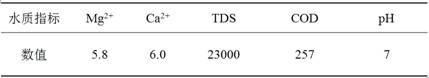
[0042] A high-salt organic wastewater includes reverse osmosis concentrated water, circulating water sewage, chemical water station drainage and some production wastewater. The water quality indicators after pretreatment are as follows:

[0043] Table 1 Water quality indicators of high-salt wastewater (unit mg / L, except pH value)

[0044]

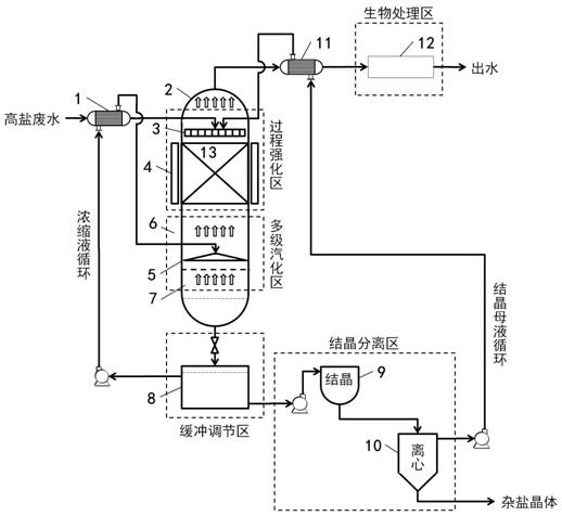
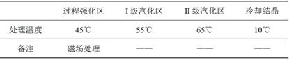
[0045] Attached figure 1 The device treats high-salt organic wastewater, the packing is corrugated metal mesh packing, the field effect is magnetic field, and the processing scale is 1.5t / h. The main process parameters are:

[0046] Table 2 Main process parameters

[0047]

[0048] After the high-salt wastewater is treated, the TDS in the effluent is 130 mg / L, and the desalination rate is 99.4%; the COD is 37 mg / L, and the COD removal rate is 85.6%. The reactor has been in operation for 6 months without obvious corrosion.

Embodiment 2~7

[0050] With embodiment 1. The difference lies in: high-salt wastewater indicators, main process parameters, etc. are different. The indicators of high-salt wastewater, main process parameters and indicators of treated effluent are shown in Table 3.

[0051] Table 3 Treatment results of high-salt wastewater

[0052]

Embodiment 8

[0054] The composition of waste water quality is the same as in Example 1. The difference is: the field effect uses ultrasonic waves. After the wastewater is treated, the TDS in the effluent is 432mg / L, and the desalination rate is 98.1%; the COD is 42mg / L, and the COD removal rate is 83.7%. After 6 months of operation, the reactor has no obvious corrosion phenomenon.


PUM

PropertyMeasurementUnit
salt rejection rateaaaaaaaaaa
clearance rateaaaaaaaaaa

Abstract

The invention relates to a method and a device for treating high-salinity organic wastewater. The method is realized through the following functional areas: a process strengthening area, a multi-stage vaporization area, a buffer regulation area, a crystallization separation area and a biological treatment area, the high-salinity organic wastewater passes through the process strengthening area and is subjected to process strengthening under the action of a filler and a field effect, and by changing the physicochemical properties of a solution, The vaporization temperature of A solvent is reduced. Then the solvent enters the multi-stage vaporization area at the lower part of the main reactor to accelerate the vaporization rate of the solvent. The buffer regulation area adjusts the liquid level of a tower kettle concentrated solution of the main reactor, and part of the concentrated solution is circulated back to the multi-stage vaporization area. The residual concentrated solution in the buffer regulation area enters the crystallization separation area, and carnallite in the concentrated solution is crystallized out. Vaporized steam is condensed, and condensate enters a biological treatment area to remove organic matter. According to the method, the salt content and COD in the high-salinity wastewater are effectively reduced, the crystallization effect is good, the energy consumption is low, and corrosion of the wastewater to equipment is weakened under low-temperature operation.

Description

technical field [0001] The invention belongs to the field of waste water treatment, and in particular relates to a treatment method and device for high-salt organic waste water. Background technique [0002] Coal chemical, petrochemical, electric power and other industries consume a lot of water, and produce varying amounts of high-salt wastewater in the production process. In environmentally sensitive areas, the discharge of high-salt wastewater will have a serious impact on the ecological environment. Effective disposal of high-salt wastewater is a difficult problem in the field of environmental protection. At present, the zero discharge of high-salt wastewater mainly adopts the process route of pretreatment + membrane concentration + evaporation and crystallization. Generally, the organic matter and hardness ions in the wastewater are removed through the pretreatment process, and then the membrane concentration device is used for reduction treatment, resulting in The hig...

Claims


Application Information

Patent Timeline
Patent Type & Authority Applications(China)
IPC IPC(8): C02F9/14C02F101/30
CPCC02F9/00C02F1/36C02F1/302C02F1/48C02F1/04C02F1/048C02F3/00C02F3/28C02F2301/08C02F2101/30
Inventor 马传军王雪清程晓东
Owner CHINA PETROLEUM & CHEM CORP
Why Eureka
Try Eureka