
3D printing resin for manufacturing low-loss antenna and application of 3D printing resin

A 3D printing, low-loss technology, applied in the field of new 3D printing resins, to simplify the production process, reduce the loss angle, and achieve good leveling

Pending Publication Date: 2021-07-20
SOUTHEAST UNIV
View PDF3 Cites 0 Cited by
  • Summary
  • Abstract
  • Description
  • Claims
  • Application Information

AI Technical Summary

Problems solved by technology

However, the traditional process can only produce some antennas with simple and regular shapes, and the cycle is long. If you use the stereolithography (SLA) technology or extrusion molding technology in 3D printing technology, you can fuse polypropylene and photosensitive resin to directly manufacture antennas. 3D printing technology will greatly shorten the printing cycle, and the operation of 3D printing technology is relatively simple, the precision is high and no mold is needed, which simplifies the process flow

Method used


Image

  • 3D printing resin for manufacturing low-loss antenna and application of 3D printing resin
  • 3D printing resin for manufacturing low-loss antenna and application of 3D printing resin
  • 3D printing resin for manufacturing low-loss antenna and application of 3D printing resin

Examples


Embodiment 1

[0059] The low-loss antenna material used for photocuring 3D printing in this embodiment includes the following raw materials in parts by weight:

[0060]

[0061] In this embodiment, the preparation method of the light-cured 3D printing low-loss antenna is as follows:

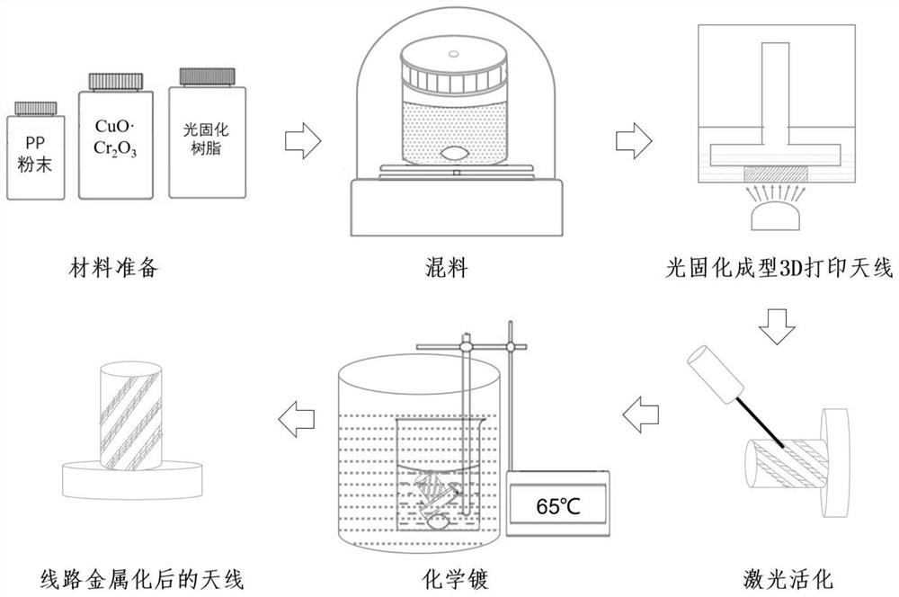
[0062] (1) Mix 70g polyethylene glycol (PEG) and 70g ethylene glycol diacrylate (HDDA) at room temperature and stir evenly to obtain a photocurable resin substrate;

[0063] (2) Add 50 g of polypropylene (PP) powder to the product in (1) several times in a small amount, stir at high speed in a vacuum environment until mixed, and obtain a low-loss photocurable resin;

[0064] (3) Add 10 g of laser-activatable (LDS) metal compound powder to the product in (2), and stir at high speed in a vacuum environment until the mixture is evenly mixed to obtain a laser-activatable low-loss photocurable resin.

[0065] (4) Add 2g of photosensitizer (TPO) to the product in (3) under the condition of avoiding light, and st...

Embodiment 2

[0080] The low-loss antenna material in this embodiment includes the following raw material components in parts by weight:

[0081]

[0082] The material preparation method of the low-loss antenna material of this embodiment is the same as that of Embodiment 1, the only difference is that due to the high content of PP powder, it needs to be diluted with ethanol to help the material to mix and stir better, and because ethanol is volatile , whose mass is not included in the total mass of the material. The PP content of the material can reach 65%, and the loss angle of the obtained low-loss photocurable resin is about 0.0018. .

[0083] The 3D printing method used in this example is extrusion molding: put the prepared material into an opaque metal dispensing syringe in the dark, with a needle diameter of 1.25 mm, use the FDM slicing software to slice the model, and select in the software Corresponding to the diameter of the needle, the thickness of the printing layer is 0.4 / ...


PUM


Abstract

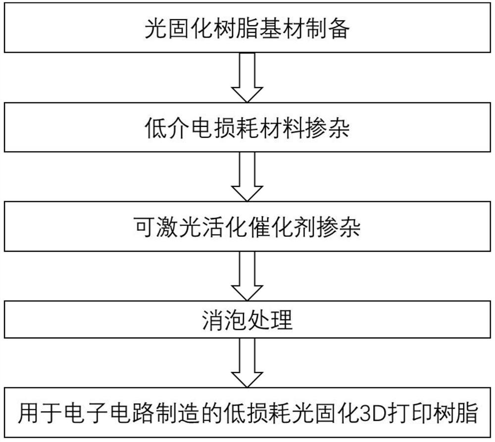
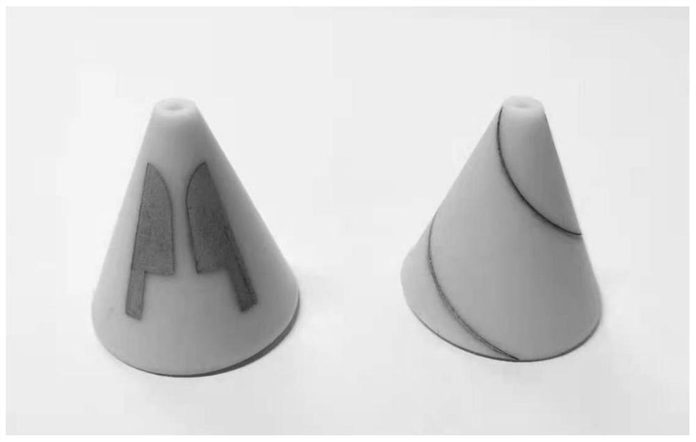
The invention discloses 3D printing resin for manufacturing a low-loss antenna and application of the 3D printing resin. The 3D printing material comprises a light-cured resin prepolymer, a photoinitiator, a reactive diluent, a dispersing agent, a laser-activatable metal compound and low-loss polymer powder. The preparation method of the material comprises the following steps: preparing the light-cured resin base material; doping a low dielectric loss material; doping a catalyst capable of being activated by laser; and performing defoaming treatment. The processing method of the low-loss antenna comprises the following steps: 1, constructing an antenna model by using a CAD tool; 2, carrying out antenna matrix 3D printing by using the prepared light-cured resin material; 3, conducting laser activation; and 5, metalizing the conductive circuit of the antenna. According to the functional 3D printing material for manufacturing the low-loss antenna, the capability of manufacturing electronic circuit products through 3D printing is greatly improved, and the functional 3D printing material can be applied to the fields of aerospace, 5G communication, intelligent automobiles and the like.

Description

technical field [0001] The invention relates to a functional 3D printing material that can be used in the manufacture of low-loss antennas, specifically a novel 3D printing resin and a process method. Background technique [0002] The arrival of the 5G era has greatly increased the transmission speed of the signal, which is much faster than the 4G signal. This puts forward higher requirements for wireless equipment. As an important device for radiating and receiving radio waves, the antenna must ensure that it has little interference with the signal. It is also required that the dielectric constant of the material used should be small, and the loss of the signal should be low, so as to ensure that the large data transmission is not disturbed. At present, the materials for preparing such low-loss antennas are mostly high polymers with low loss angle and high-strength mechanical properties, and the methods for preparing low-loss antennas from them are mainly traditional pressi...

Claims


Application Information

Patent Timeline
IPC IPC(8): C08F283/06C08F255/02C08F222/14C08F2/48C08K3/22B33Y70/10
CPCC08F283/06C08F255/02C08F2/48C08K3/22B33Y70/10C08F222/102
Inventor 李霁邓李硕刘森叶鸣风刘佳琪王培任王国祺
Owner SOUTHEAST UNIV
Learn More