Microfluid distributor and multi-channel parallel amplification fluid uniform distribution method

A fluid distribution and distributor technology, applied in the field of flow chemistry, can solve the problems of high processing and manufacturing requirements, large pressure drop, and poor practicability, and achieve the effects of wide range of operating conditions, realization of processing throughput, and convenient processing and manufacturing

Active Publication Date: 2021-07-23
FUDAN UNIV
View PDF4 Cites 2 Cited by
  • Summary
  • Abstract
  • Description
  • Claims
  • Application Information

AI Technical Summary

Problems solved by technology

Commonly used tree branch geometry (Li et al., Lab on Chip, 2009, 9, 2715-2721; Hoang et al., Chemical Engineering Journal, 2014, 236, 545-554; Mas et al., Industrial & Engineering Chemistry Research, 2006 , 45,8036-8042) there are problems such as uneven flow distribution, large pressure drop and high energy consumption in each branch channel, especially when the symmetry is broken, it will seriously affect the flow distribution
In addition, there are disadvantages such as high process

Method used


Image

  • Microfluid distributor and multi-channel parallel amplification fluid uniform distribution method
  • Microfluid distributor and multi-channel parallel amplification fluid uniform distribution method
  • Microfluid distributor and multi-channel parallel amplification fluid uniform distribution method

Examples


Embodiment 1

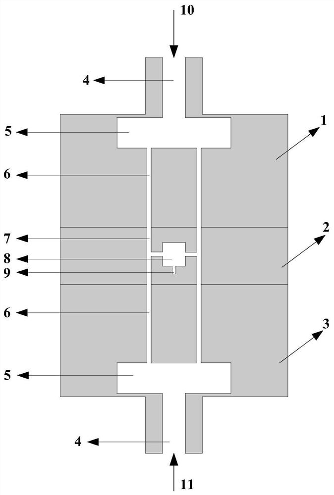
[0056] The microfluid distributor used in this embodiment is as figure 1 shown. In order to measure the uniformity of the fluid flow distribution among multiple parallel channels, the fluid flow distribution characteristics of the fluid flow distribution module 1 and the fluid flow distribution module 3 are separately measured and evaluated first, that is, the fluid flow distribution module 1, the fluid mixing module 2 and the fluid flow distribution module Module 3 does not assemble together.

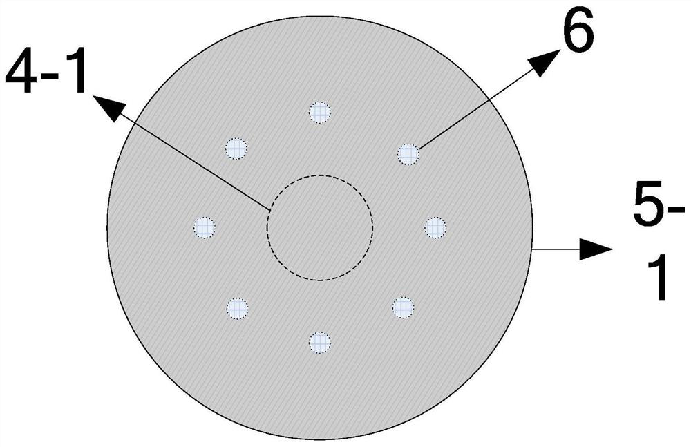
[0057] The inner diameter of the fluid inlet channel 4 of the fluid flow distribution module 1 is 1 mm, and the fluid flow distribution chamber 5 is a cylinder with an inner diameter of 20 mm and a height of 2 mm. The chamber 5 communicates, and the lower bottom surface of the fluid flow distribution chamber 5 distributes eight parallel fluid distribution channels 6 evenly along the circumference of equal radius. The distance between the center of the lower bottom surface of the flow...

Embodiment 2

[0061] The fluid flow distribution module 1 and the fluid flow distribution module 3 used are the same as in the embodiment 1, except that in this embodiment, ethyl acetate is pumped into the fluid flow distribution module 1 from the fluid inlet channel 4, and after measurement, the eight fluid distribution channels The outflow fluid flow rate is exactly the same, the deviation between the maximum flow rate and the minimum flow rate is less than 0.05%, and the pressure at the outlet of the eight fluid distribution channels detected by a precision pressure gauge is exactly the same, the deviation between the maximum pressure and the minimum pressure is less than 0.05%, and the inlet of the fluid inlet channel 4 The pressure difference at the outlet of the fluid distribution channel (6) is 98Pa. The result of the fluid flow distribution module 3 is the same as that of the fluid flow distribution module (1.

[0062] Using a conventional fluid distributor with a tree-shaped branch ...

Embodiment 3

[0065] The fluid flow distribution module 1 and the fluid flow distribution module 3 used are the same as in the embodiment 1, except that in this embodiment, the silicone oil is pumped into the fluid flow distribution module 1 from the fluid inlet channel 4, and after measurement, the fluid flow out from the eight fluid distribution channels The fluid flow rate is exactly the same, the deviation between the maximum flow rate and the minimum flow rate is less than 0.05%, and the pressure at the outlet of the eight fluid distribution channels detected by a precision pressure gauge is exactly the same, and the deviation between the maximum pressure and the minimum pressure is less than 0.05%. The pressure difference at the outlet of the fluid distribution channel 6 is 98Pa. The result of the fluid flow distribution module 3 is the same as that of the fluid flow distribution module 1.

[0066] Using a conventional fluid distributor with a tree-shaped branch geometry, repeating th...


PUM

PropertyMeasurementUnit
Hydraulic diameteraaaaaaaaaa
Lengthaaaaaaaaaa
Lengthaaaaaaaaaa

Abstract

The invention belongs to the technical field of flow chemistry, and particularly relates to a microfluid distributor and a multi-channel parallel amplification fluid uniform distribution method. The microfluid distributor is composed of two fluid flow distribution modules and a fluid mixing module assembled between the two fluid flow distribution modules. The fluid flow distribution module comprises a fluid inlet channel, a fluid flow distribution chamber and a fluid distribution channel; the fluid mixing module comprises a fluid mixing channel, a mixed liquid collecting chamber, a mixed liquid outlet channel and a mixed liquid outlet; and the three modules are communicated through channels. Two fluids are simultaneously input into the two fluid flow distribution modules respectively, uniformly flow into the corresponding fluid distribution channels in the two fluid flow distribution chambers respectively, then flow into the fluid mixing module, then enter the mixed liquid collecting chamber and finally flow out through the mixed liquid outlet channel. The microfluid distributor has the advantages that the operating condition range is wide, the fluid flow among a plurality of parallel fluid channels can be strictly and uniformly distributed, the pressure drop is small, and the energy consumption is low.

Description

technical field [0001] The invention belongs to the technical field of flow chemistry, and in particular relates to a microfluid distributor and a multi-channel parallel amplification fluid uniform distribution method. Background technique [0002] The technology of pumping materials and carrying out chemical reactions in microchannel reactors in a continuous flow mode is called continuous flow microreaction technology (also known as flow chemistry). Different from the traditional batch reactor, the microchannel reactor provides a micro-scale reaction space, which has the characteristics of rapid material molecular mixing, high mass and heat transfer efficiency, precise and controllable reaction process, continuous operation, high space-time efficiency and process intrinsic safety. and other unique advantages. In recent years, continuous flow micro-reaction technology has developed rapidly, and has gradually shown great potential to change the production mode of pharmaceuti...

Claims


Application Information

Patent Timeline
IPC IPC(8): B01J19/00B01F13/00
CPCB01J19/0093B01J19/0053B01F33/30
Inventor 陈芬儿程荡黄华山刘敏杰王路路
Owner FUDAN UNIV
Why Eureka
Try Eureka