
Time-to-digital converter for measuring decimal phase error of all-digital phase-locked loop

An all-digital phase-locked loop, phase error technology, applied in the direction of automatic power control, electrical components, etc., can solve problems such as deteriorating the resolution and linearity of time-to-digital converters, increasing power consumption and module area, and process evolution violations. , to achieve the effect of saving power consumption, saving chip area and wide measurement range

Active Publication Date: 2021-07-27
SOUTHEAST UNIV
View PDF3 Cites 4 Cited by
  • Summary
  • Abstract
  • Description
  • Claims
  • Application Information

AI Technical Summary

Problems solved by technology

Nyquist time-to-digital converters often have a higher sampling rate, but the on-chip mismatch becomes more serious under advanced technology, which will deteriorate the resolution and linearity of the time-to-digital converter
Although the mismatch can be reduced by increasing the size of the MOS tube, it will increase power consumption and module area at the same time, and it goes against the trend of process evolution
The oversampling time-to-digital converter based on the ring oscillator can realize mismatch shaping, and has a large dynamic range and high resolution, but still has the disadvantages of complex structure, limited bandwidth and high power consumption. , and is affected by time skew errors caused by leakage currents and charge sharing, deteriorating its performance

Method used


Image

  • Time-to-digital converter for measuring decimal phase error of all-digital phase-locked loop
  • Time-to-digital converter for measuring decimal phase error of all-digital phase-locked loop
  • Time-to-digital converter for measuring decimal phase error of all-digital phase-locked loop

Examples


Embodiment Construction

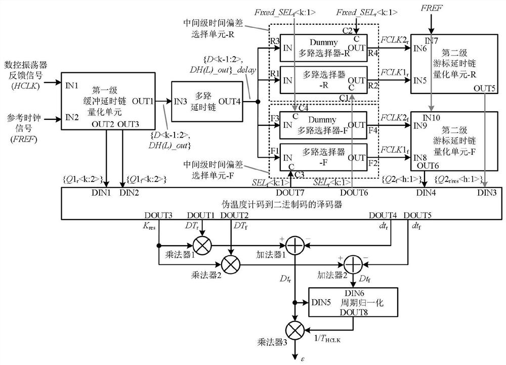
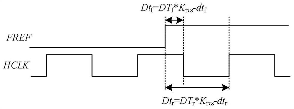
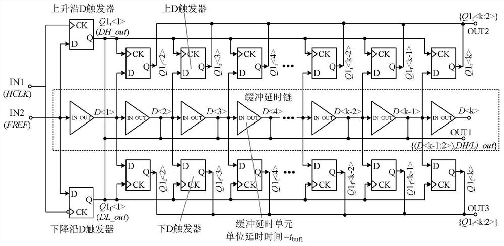
[0033] see figure 1 , the present invention is based on the cascade structure of the buffer delay chain and the vernier delay chain, including a core quantization unit and a decoding unit, and the core quantization unit includes a first-level buffer delay chain quantization unit, a multi-way delay chain, and an intermediate stage time The deviation selection unit and the second-stage vernier delay chain quantization unit; the decoding unit includes a decoder from pseudo-thermometer code to binary code, a logic operation unit and a cycle normalization unit. The input terminals IN1 and IN2 of the quantization unit of the first-stage buffer delay chain are respectively connected to the numerically controlled oscillator feedback signal HCLK and the reference clock signal FREF, and the output terminal OUT1 is for each stage of the buffer delay unit from the second stage to the k-1th stage output signal D (i=2,3,...,k-1) and the extracted HCLK rising edge / falling edge signal DH(...


PUM


Abstract

The invention discloses a time-to-digital converter for measuring a decimal phase error of an all-digital phase-locked loop, which is based on a cascade structure of a buffer delay chain and a vernier delay chain, adopts a time window technology, delays a reference clock signal with lower frequency, and extracts a rising / falling edge of a single clock signal for signal detection; a circuit multiplexing technology is adopted, a rising / falling edge detection delay chain of the first-stage quantization unit is multiplexed, and meanwhile, a coarse quantization time error detection circuit and a two-stage resolution ratio scale factor detection circuit of the second-stage quantization unit are multiplexed; meanwhile, coarse quantization and fine quantization are carried out on the time deviation between the rising edge of the reference clock signal FREF and the nearest rising edge and falling edge of the feedback signal HCLK of the numerically controlled oscillator, so that a high-precision quantization result of the HCLK signal period is obtained. The measurement range is larger than 1.6 ns, the resolution ratio is higher than 2.8 ps, and the differential nonlinearity is smaller than 0.31 LSB.

Description

technical field [0001] The present invention relates to all-digital phase-locked loop technology, in particular to a time-to-digital converter for measuring the fractional phase error of the all-digital phase-locked loop, which can be used for the quantization of the phase error signal output by the phase detector in the all-digital phase-locked loop system, and belongs to field of digital integrated circuits. Background technique [0002] In recent years, with the continuous improvement of semiconductor technology, the feature size of MOS transistors has been continuously reduced, and the performance and power consumption of time domain and digital domain circuits have been continuously improved. Strong ability, short development cycle, low production cost, and easy transplantation have become an important direction for the development of phase-locked loop technology. The time-to-digital converter can convert the phase difference between the reference clock and the feedbac...

Claims


Application Information

Patent Timeline
Patent Type & Authority Applications(China)
IPC IPC(8): H03L7/18
CPCH03L7/18
Inventor 李智群姚艳陈伯凡李振南王晓伟
Owner SOUTHEAST UNIV
Learn More