Safety protection system for air separation
A technology of safety protection and air separation, applied in the direction of measuring devices, instruments, etc., can solve problems such as safe operation and emergency prevention hidden dangers, suffocation accidents, leakage and diffusion of storage tanks, etc., and achieve the effect of timely emergency response
- Summary
- Abstract
- Description
- Claims
- Application Information
AI Technical Summary
Problems solved by technology
Method used
Image

Examples
Embodiment 1
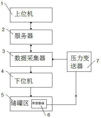
[0031] combine figure 1 and figure 2 , a safety protection system for air separation, including a storage tank area 5, including a host computer 1 and a lower computer 4 controlling the storage tank area 5, the sensor group 6 in the storage tank area 5 collects the corresponding The parameters are transmitted to the data collector 3 through the pressure transmitter 7, and the data collector 3 uploads the collected data to the host computer 1 through the server 2, and the host computer 1 passes the control command through the data collector according to the corresponding data 3 to the lower computer 4, and the lower computer 4 controls the storage tank area 5 to make adjustments.
[0032] Through the pressure transmitter and the data collector, the parameter values of the indicators in the dangerous source of the storage tank are collected in real time, and the data is judged and processed by the upper computer. When the indicators reach the specified limit value, the upper...
Embodiment 2
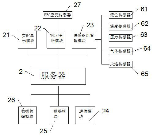
[0036] On the basis of Example 1, during the long-term operation of the storage tank, due to the filling and extraction of internal gas and the influence of the natural environment, it is inevitable that deformation will occur to varying degrees. When the storage tank is deformed to a certain extent, the stress concentration area of the storage tank The probability of cracking and damage will be greatly increased, and the risk of leakage will also be increased. Therefore, an optical fiber grating strain sensor 27 is installed on the storage tank to detect the stress situation of each storage tank in the storage tank area 5. The optical fiber grating strain sensor 27 The sensor 27 is connected to the demodulator through a single-mode optical fiber, and the fiber grating strain sensor 27 transmits the received strain signal to the demodulator through the optical cable, and the demodulator demodulates the wavelength offset and transmits it to the host computer 1.
[0037] When ...
Embodiment 3
[0041] On the basis of Example 1, when the liquid substance in the storage tank in the storage tank area leaks, it is accompanied by a flash phenomenon, and part of the liquid substance is converted into steam and suspended in the air, forming a mixed heavy gas cloud. After heat absorption and evaporation, the cloud cluster is transformed into a gaseous state of matter and a mixed gas cloud cluster of air, forming a neutral gas cloud cluster. Therefore, the judgment of the continuous leakage rate Q of the liquid material in the storage tank in the server is as follows:
[0042] Q=S·P·{k·M·[2 / (k+1)] (k+1) / (k-1) / RT} 1 / 2 ;
[0043] Where S is the leakage area (m2), P is the pressure in the storage tank (Pa), M is the molecular weight of the corresponding gas (kg / mL), k is the adiabatic index, T is the absolute temperature of the corresponding gas (K), and R is Gas constant, T is the absolute temperature of the gas.
[0044] During the leakage process, the pressure in the stor...
PUM
 Abstract
Description
Claims
Application Information
 - Generate Ideas
- Intellectual Property
- Life Sciences
- Materials
- Tech Scout
- Unparalleled Data Quality
- Higher Quality Content
- 60% Fewer Hallucinations
Browse by: Latest US Patents, China's latest patents, Technical Efficacy Thesaurus, Application Domain, Technology Topic, Popular Technical Reports.
© 2025 PatSnap. All rights reserved.Legal|Privacy policy|Modern Slavery Act Transparency Statement|Sitemap|About US| Contact US: help@patsnap.com