Peak regulation power generation system and method coupled with compressed air energy storage

A technology for compressed air energy storage and power generation systems, which is applied to engine components, machines/engines, steam engine installations, etc., can solve the problems of increased initial investment, limited steam parameters, and low waste heat utilization efficiency, and achieves increased power on the grid and reduced power consumption. The effect of oxygen content and power saving

Active Publication Date: 2021-08-03
ELECTRIC POWER RES INST OF STATE GRID ZHEJIANG ELECTRIC POWER COMAPNY +1
View PDF6 Cites 5 Cited by
  • Summary
  • Abstract
  • Description
  • Claims
  • Application Information

AI Technical Summary

Problems solved by technology

However, the addition of waste heat boilers, steam turbines and other equipment not only requires additional initial investment, but also due to the limited steam parameters, the efficiency of waste heat utilization is relatively low

Method used


Image

  • Peak regulation power generation system and method coupled with compressed air energy storage
  • Peak regulation power generation system and method coupled with compressed air energy storage

Examples


Embodiment 1

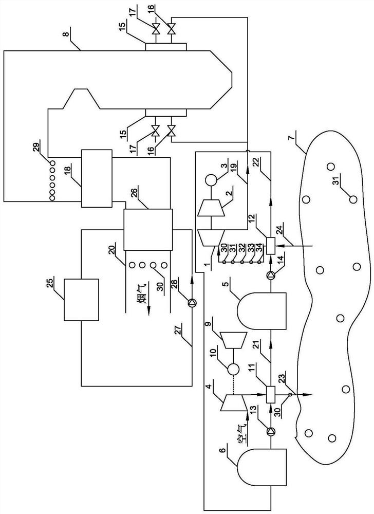
[0052] Please refer to the attached figure 1 It is a schematic diagram of the peak-shaving power generation system coupled with compressed air energy storage in the present invention. The system includes gas turbine 1, main compressor 2, gas turbine generator 3, electric compressor 4, hot tank 5, cold tank 6, storage space 7, coal-fired boiler 8, coal-fired steam turbine 9 and coal-fired generator 10.

[0053] The electric compressor 4 is connected to a coal-fired generator 10 , and the coal-fired generator 10 is connected to a coal-fired steam turbine 9 .

[0054] The electric compressor 4 , the first heat exchanger 11 , and the storage space 7 are connected through a gas storage pipeline 23 , and the storage space 7 , the second heat exchanger 12 , and the gas turbine 1 are connected through an air release pipeline 24 . The gas turbine 1 is connected to the main compressor 2, and the main compressor 2 is connected to the gas turbine generator 3.

[0055] The heat storage ...

Embodiment 2

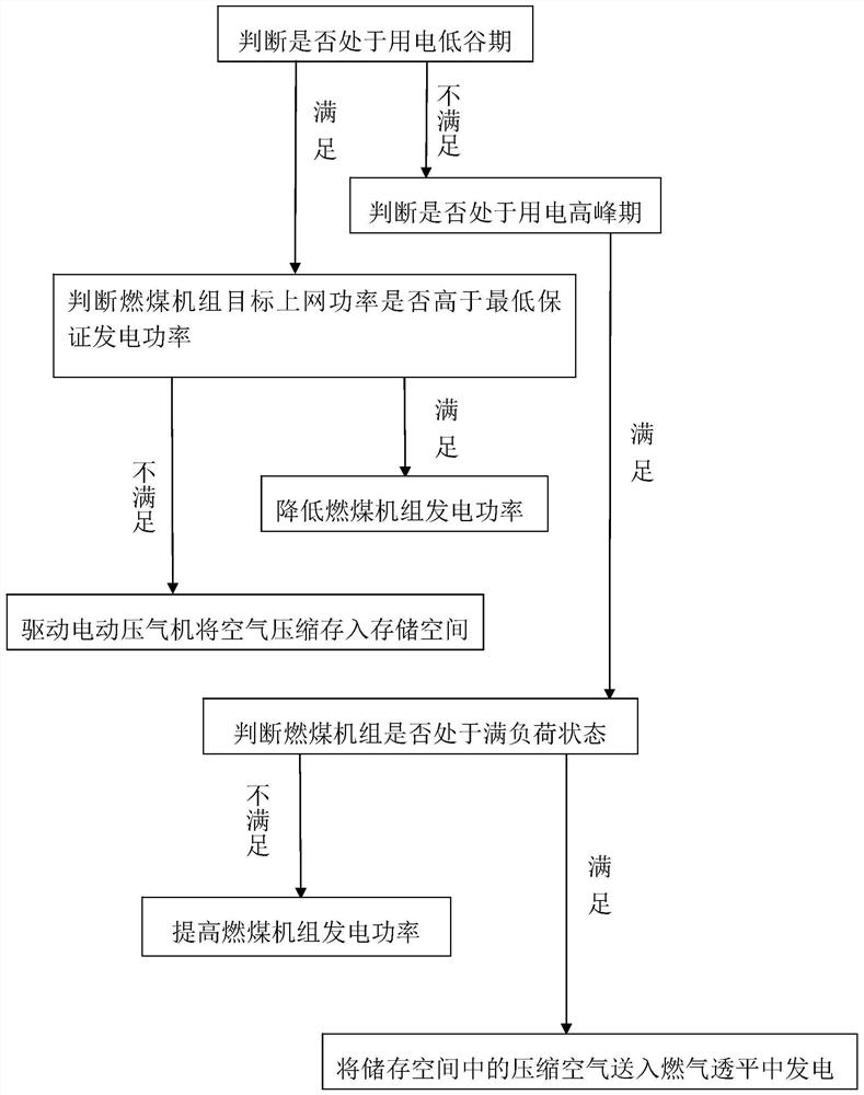
[0077] Please refer to the attached figure 2 It is a schematic diagram of a peak-shaving power generation method coupled with compressed air energy storage in the present invention, which adopts the peak-shaving power generation system coupled with compressed air energy storage described in Embodiment 1, and the peak-shaving power generation method includes the following steps:

[0078] Step 1, judge whether it is in the low power consumption period, if it is satisfied, then go to step 3, if not, go to step 2;

[0079] Step 2, judging whether it is in the peak period of electricity consumption, if it is satisfied, go to step 6;

[0080] Step 3. At this time, the gas turbine is in the outage state, and it is judged whether the target on-grid power of the coal-fired unit is higher than the minimum guaranteed power generation at this time. If it is satisfied, perform step 4. If not, perform step 5;

[0081] Step 4, reduce the power generation of coal-fired units;

[0082] Step...


PUM


Abstract

The invention discloses a peak regulation power generation system and method coupled with compressed air energy storage. With the development and utilization of large-scale renewable energy sources, the peak-valley difference of a power grid is increasingly increased, and the bearing capacity is also limited. According to the technical scheme, when the power grid is in a power consumption valley period, air is compressed through power generated by a coal-fired unit and then stored in a storage space, and on the premise that it is guaranteed that the actual generation power of the coal-fired unit is higher than the minimum guaranteed generation power, the on-grid power of the coal-fired unit is effectively reduced; and when the power grid is in a power consumption peak period, the compressed air in the storage space is fed into a gas turbine for power generation, so that the power consumption of a main compressor is reduced, the on-grid power of the gas turbine is improved, and the natural gas consumption is reduced. According to the peak regulation power generation system and method coupled with compressed air energy storage, support can be provided for peak load shifting of the power grid, so that the renewable energy consumption capability is improved, and the usage amount of high-grade energy such as natural gas can be reduced on the premise that the on-grid power of the system meets the power grid adjustment requirement.

Description

technical field [0001] The invention belongs to the field of generator sets, in particular to a peak-shaving power generation system and method coupled with compressed air energy storage. Background technique [0002] In recent years, the contradiction between energy supply and demand and environmental pollution have become global problems. Vigorously developing renewable energy has become an important direction to alleviate this problem, and it is also very important for my country's energy transformation. However, the large-scale grid integration of intermittent renewable energy such as wind power and photovoltaics has also aggravated the difficulty of grid regulation, which not only affects the safe operation of the grid, but also limits the capacity of renewable energy consumption. Compressed air energy storage has been applied on a certain scale in foreign countries, and its technological development not only helps the power grid to "shave peaks and fill valleys", but a...

Claims


Application Information

Patent Timeline
Patent Type & Authority Applications(China)
IPC IPC(8): F01D15/10F01D21/00F01K11/02F01K13/00F01K13/02F04B37/12
CPCF01D15/10F01D21/003F01D21/00F04B37/12F01K11/02F01K13/00F01K13/02F01K13/003Y02E60/16
Inventor 吕洪坤童家麟应明良茅建波刘文胜徐小琼丁历威
Owner ELECTRIC POWER RES INST OF STATE GRID ZHEJIANG ELECTRIC POWER COMAPNY
Why Eureka
Try Eureka