
Efficient electric combustion furnace for collecting fire coal PM2.5

A PM2.5, electric furnace technology, applied in the combustion of solid fuel, air/fuel supply for combustion, combustion method, etc., can solve problems such as affecting combustion state, insufficient air supply, affecting detection results, etc., to reduce Pollution, the effect of improving combustion efficiency

Active Publication Date: 2021-08-20
ZUNYI MEDICAL UNIVERSITY
View PDF10 Cites 0 Cited by
  • Summary
  • Abstract
  • Description
  • Claims
  • Application Information

AI Technical Summary

Problems solved by technology

[0003]The existing energy is mainly coal, and the smoke, sulfur dioxide, carbon monoxide and other harmful substances released during the combustion of coal will cause bronchitis, bronchial asthma, For diseases such as emphysema and lung cancer, it is necessary to conduct experimental research on coal PM2.5. At present, most of the burners on the market are used for household heating, which are not suitable for laboratory research on PM2.5. In order to solve the above Technical problem, Chinese patent CN 110394014A discloses a solid fuel PM2.5 detection experimental device, which realizes the combustion of materials through electric heating, and then installs a PM2.5 detection device at the discharge end to realize PM2.5 experimental detection However, in the disclosed structure, the intake pipe structure is set as an L-shaped structure, resulting in insufficient air supply, affecting the combustion state, and thus affecting the final detection result

Method used


Image

  • Efficient electric combustion furnace for collecting fire coal PM2.5
  • Efficient electric combustion furnace for collecting fire coal PM2.5
  • Efficient electric combustion furnace for collecting fire coal PM2.5

Examples


Embodiment 1

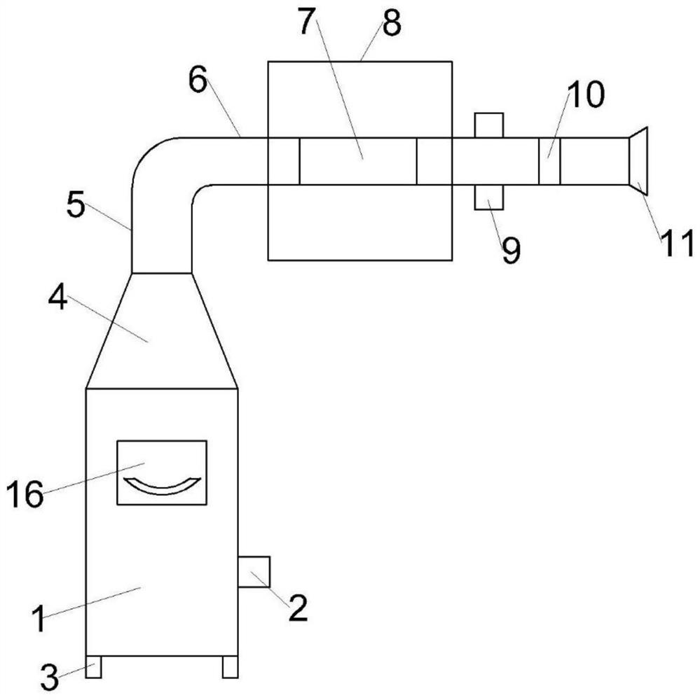
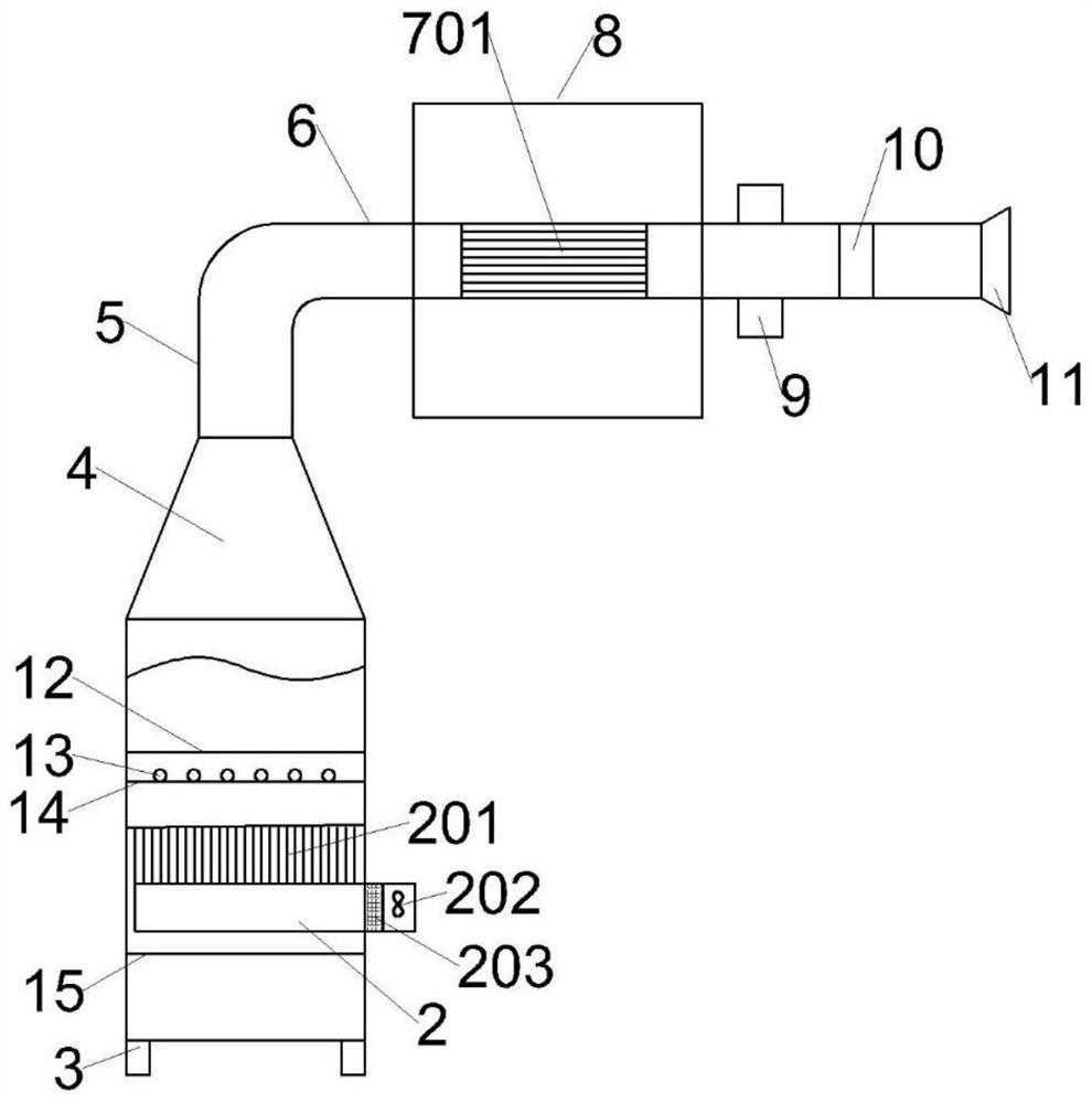
[0035] refer to Figure 1-4 As shown in the figure, this embodiment provides a high-efficiency electric combustion furnace for collecting coal-fired PM2.5, including a furnace body 1, the top of the furnace body 1 is connected with a flow velocity acceleration channel 4, and the top of the flow velocity acceleration channel 4 is connected with an exhaust pipe 6. The air pipe 6 is sequentially provided with a cooling pipe assembly 7, a PM2.5 detection end 9, and an exhaust filter element 10 along the air flow direction;

[0036] The furnace body 1 is fixedly connected with a heating wire 13, a support plate 14, an air inlet channel 2, and an anti-heating plate 15 sequentially from top to bottom. The side wall of the furnace body 1 is detachably connected with a feeding baffle 16, which is vertically fixed and connected. There is a material storage plate 12, the material storage plate 12 is a hollow structure, the material storage plate 12 is located above the heating wire 13, a...

Embodiment 2

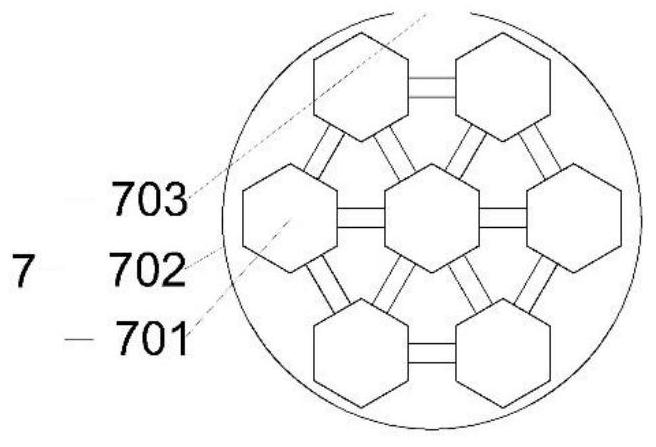
[0055] refer to Figure 5-6 As shown, the difference between the high-efficiency electric combustion furnace of this embodiment and the first embodiment is only that the inner wall of the exhaust pipe 6 is provided with a first reducing protrusion 601, and the inner wall of the shunt pipe 701 is provided with a plurality of second reducing protrusions 7011, The first variable diameter protrusion 601 divides the exhaust pipe 6 into two opposite conical truncated structures, and the second variable diameter protrusion 7011 divides the inner wall of the shunt pipe 701 into several conical truncated structures. According to the Laval structure principle, the airflow When passing through the first reducing protrusion 601 and the second reducing protrusion 7011, there will be a process of compression and expansion, which will increase the flow rate of the airflow through the exhaust pipe 6 and the shunt pipe 701, thereby enhancing the overall electrical The air intake and air circul...

Embodiment 3

[0057] refer to Figure 7 As shown, the difference between the high-efficiency electric combustion furnace of this embodiment and the first embodiment is only that the furnace body 1 and the flow velocity acceleration channel 4 are detachably connected, and the outer side wall of the furnace body 1 is fixedly connected with a first fixed block 101, and the flow velocity acceleration channel 4. A second fixing block 401 is fixedly connected to the outer side wall. The top of the second fixing block 401 is rotatably connected with a clamping wrench 402. The middle of the clamping wrench 402 is rotatably connected with a clamping buckle 403, and the clamping buckle 403 is away from the clamping wrench 402. One side is set in contact with the bottom of the second fixing block 401, and the flow velocity acceleration channel 4 is made of high temperature resistant transparent material, which is convenient for observing the combustion situation in the furnace body 1, and the flow velo...


PUM


Abstract

The invention relates to the technical field of experimental equipment, in particular to an efficient electric combustion furnace for collecting fire coal PM2.5. The efficient electric combustion furnace comprises a furnace body, the top of the furnace body communicates with a flow speed acceleration channel, the top of the flow speed acceleration channel is communicated with an exhaust pipe, and a cooling pipe assembly, a PM2.5 detection end and an exhaust filter element are sequentially arranged on the exhaust pipe in the airflow circulation direction; the furnace body is sequentially and fixedly connected with a heating wire, a supporting plate, an air inlet channel and a heat reflecting plate from top to bottom, the side wall of the furnace body is detachably connected with a feeding baffle, the feeding baffle is vertically and fixedly connected with a material storage plate, the material storage plate is of a hollow structure and is located above the heating wire, and the air inlet channel penetrates through the side wall of the furnace body; and an air supply structure for promoting uniform combustion is arranged on the air inlet channel. According to the efficient electric combustion furnace for collecting the fire coal PM2.5 provided by the invention, high-efficiency combustion of the fire coal can be realized, and the purpose of accurately measuring PM2.5 of the fire coal is realized.

Description

technical field [0001] The invention relates to the technical field of experimental equipment, in particular to a high-efficiency electric combustion furnace for collecting coal-fired PM2.5. Background technique [0002] PM2.5 is mainly converted from sulfur and nitrogen oxides, and these gaseous pollutants are often caused by the burning of fossil fuels (coal, oil, etc.) and garbage by humans. Compared with the coarser atmospheric particles, the fine particles produced are small in size, rich in a large amount of toxic and harmful substances, and have a long residence time in the atmosphere and a long transportation distance, so they have an impact on human health and the quality of the atmospheric environment. bigger. Studies have shown that the smaller the particle is, the greater the harm to human health, because the smaller the diameter, the deeper the part that enters the respiratory tract, and the harm of fine particles to human health. Bronchioles and alveoli direc...

Claims


Application Information

Patent Timeline
IPC IPC(8): F23B60/02F23B90/00F23L1/00F23J15/06F23J15/02
CPCF23B60/02F23B90/00F23L1/00F23J15/06F23J15/025F23J2217/10
Inventor 俞捷许洁李克彬胡斌丽唐清红
Owner ZUNYI MEDICAL UNIVERSITY
Learn More