
Inner cavity sub-wavelength grating liquid crystal tunable vertical cavity surface emitting laser and preparation method thereof

A technology of vertical cavity surface emission and sub-wavelength grating, which is applied in the direction of lasers, semiconductor lasers, laser components, etc., can solve the problem of wavelength tuning range and tuning ratio limitation of liquid crystal tunable devices, affecting the coupling between semiconductor cavity and liquid crystal cavity, and poor performance Stability and other issues, to achieve the effect of increasing the wavelength tuning range, increasing the energy of the light field, and improving the coupling

Pending Publication Date: 2021-08-20
BEIJING UNIV OF TECH
View PDF6 Cites 0 Cited by
  • Summary
  • Abstract
  • Description
  • Claims
  • Application Information

AI Technical Summary

Problems solved by technology

Previous studies have shown that VCSEL lasers can be tuned in wavelength through micro-mechanical (MEMS), including electrothermal tuning, electrostatic tuning, piezoelectric tuning, etc., but this micro-mechanical structure is susceptible to external factors such as temperature and resonance during the tuning process factors, unstable performance and high cost
Compared with the mechanical tuning method, the use of liquid crystal (LC) materials not only achieves wavelength tuning, but also has the advantages of stable mechanical properties and high reliability. However, the high reflectivity of the semiconductor / LC interface affects the coupling between the semiconductor cavity and the liquid crystal cavity. The wavelength tuning range and tuning ratio of liquid crystal tunable devices are limited

Method used


Image

  • Inner cavity sub-wavelength grating liquid crystal tunable vertical cavity surface emitting laser and preparation method thereof
  • Inner cavity sub-wavelength grating liquid crystal tunable vertical cavity surface emitting laser and preparation method thereof
  • Inner cavity sub-wavelength grating liquid crystal tunable vertical cavity surface emitting laser and preparation method thereof

Examples


Embodiment Construction

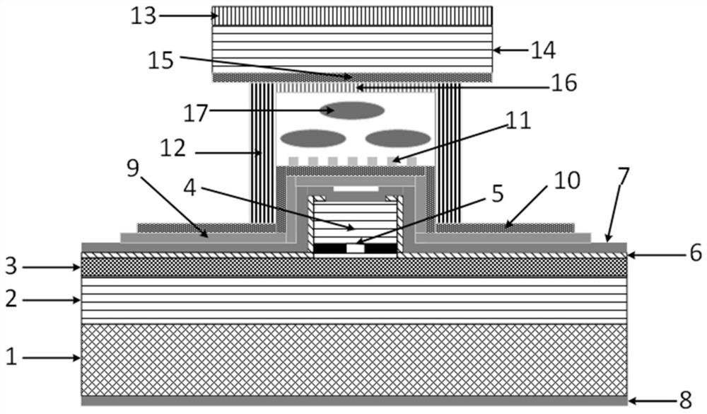
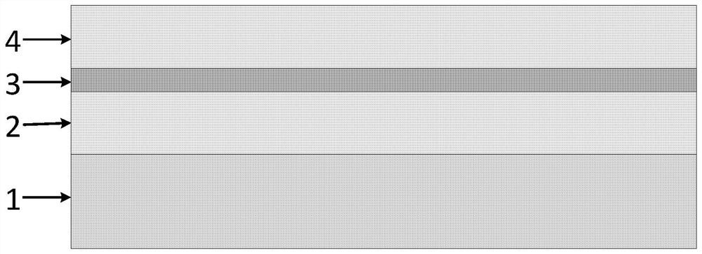
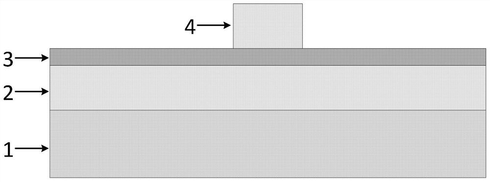
[0047] In order to make the purpose, technical solutions and advantages of the present disclosure clearer, the following combination figure 2 -- Figure 16 The preparation method of subwavelength grating liquid crystal tunable vertical cavity surface emitting laser is introduced in detail:

[0048] Step 1. Use metal organic chemical vapor deposition (MOCVD) to alternately grow n-Al on the n-type GaAs substrate 0.9 Ga 0.1 A total of 26 pairs of As layer and n-GaAs layer constitute the lower DBR; re-grow GaAs / In 0.2 Ga 0.8 As quantum well structure constitutes the active region; re-growth Al 0.98 Ga 0.02 The As layer forms an oxidation-limited layer, which limits the distribution of current and light field in the active region; re-grows heavily doped p-type AlGaAs, which facilitates the formation of good ohmic contact with the injection electrode;

[0049] Step 2. Lithographically etch the laser array pattern on the epitaxial wafer grown in step 1. Use RIE etching to etch...


PUM

PropertyMeasurementUnit
thicknessaaaaaaaaaa
depthaaaaaaaaaa
thicknessaaaaaaaaaa

Abstract

The invention discloses an inner cavity sub-wavelength grating liquid crystal tunable vertical cavity surface emitting laser and a preparation method thereof, which relate to the field of semiconductor lasers and liquid crystal physics. The laser comprises a Half-Vcsel part with a sub-wavelength grating, a basic semiconductor laser structure for emitting laser, and a liquid crystal microcavity part. Theliquid crystal microcavity part mainly uses electrically controlled birefringence characteristic of liquid crystal, the refractive index is changed along with the change of an applied electric field, and wavelength tuning is realized by combining with Half-Vcsel. The wavelength tuning range and the wavelength tuning efficiency of the liquid crystal tunable VCSEL can be improved, the high reflectivity of a semiconductor / LC interface is reduced, coupling of a semiconductor cavity and a liquid crystal cavity is improved, light field energy in a liquid crystal layer is improved, and single-polarization output can be achieved.

Description

technical field [0001] The invention relates to the fields of semiconductor lasers and liquid crystal physics, in particular to an inner cavity subwavelength grating liquid crystal tunable vertical cavity surface emitting laser and a preparation method thereof. Background technique [0002] Tunable vertical cavity surface emitting laser (VCSEL) has the advantages of circular symmetrical spot, easy two-dimensional integration, wide wavelength tuning range and high-speed modulation, so it is widely used in optical communication, biosensing, medical imaging scanning and other fields. Previous studies have shown that VCSEL lasers can be tuned in wavelength through micro-mechanical (MEMS), including electrothermal tuning, electrostatic tuning, piezoelectric tuning, etc., but this micro-mechanical structure is susceptible to external factors such as temperature and resonance during the tuning process Influenced by factors, the performance is unstable and the cost is high. Compare...

Claims


Application Information

Patent Timeline
Patent Type & Authority Applications(China)
IPC IPC(8): H01S5/183H01S5/10G02F1/1335G02F1/1337
CPCH01S5/18302H01S5/18386H01S5/1092H01S5/1096G02F1/133504G02F1/133723G02F1/133711H01S2304/00H01S2304/04
Inventor 关宝璐王志鹏张峰
Owner BEIJING UNIV OF TECH
Learn More