Two-stage centrifugal compressor for fuel cell

A centrifugal compressor and fuel cell technology, applied in fuel cells, circuits, electrical components, etc., can solve the problems of increased compressor power consumption, reduced fuel cell output power, and difficulty in system integration

Pending Publication Date: 2021-08-31
XECA TURBO TECH (BEIJING) CO LTD
View PDF0 Cites 2 Cited by
  • Summary
  • Abstract
  • Description
  • Claims
  • Application Information

AI Technical Summary

Problems solved by technology

[0003] 1. The increase in the pressure ratio of the compression system leads to an increase in the power consumption of the compressor
The fuel cell air compressor is driven by the output power of the fuel cell. After using a two-stage air compressor, the power consumption of the compressor increases, which reduces the output power of the fuel cell.
At the same time, the exhaust temperature of the fuel cell is about 100-200°C, the exhaust pressure is high, and the exhaust gas has high energy, which has not been effectively utilized
[0004] 2. At present, some single-stage air compressors use exhaust turbines to recover exhaust energy, but for two-stage compressors, adding exhaust turbines will lead to difficulty in system integration and increase in mass and volume

Method used


Image

  • Two-stage centrifugal compressor for fuel cell
  • Two-stage centrifugal compressor for fuel cell
  • Two-stage centrifugal compressor for fuel cell

Examples


Embodiment 1

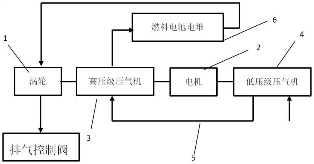
[0028] Such as figure 1 Shown: a two-stage centrifugal compressor for fuel cells, including a turbine 1, a motor 2, a high-pressure compressor 3, a low-pressure compressor 4, connecting pipelines and a fuel cell stack 6, and the turbine 1 is radial turbine.

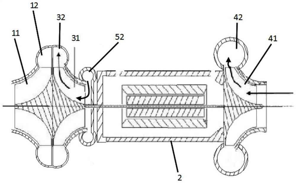
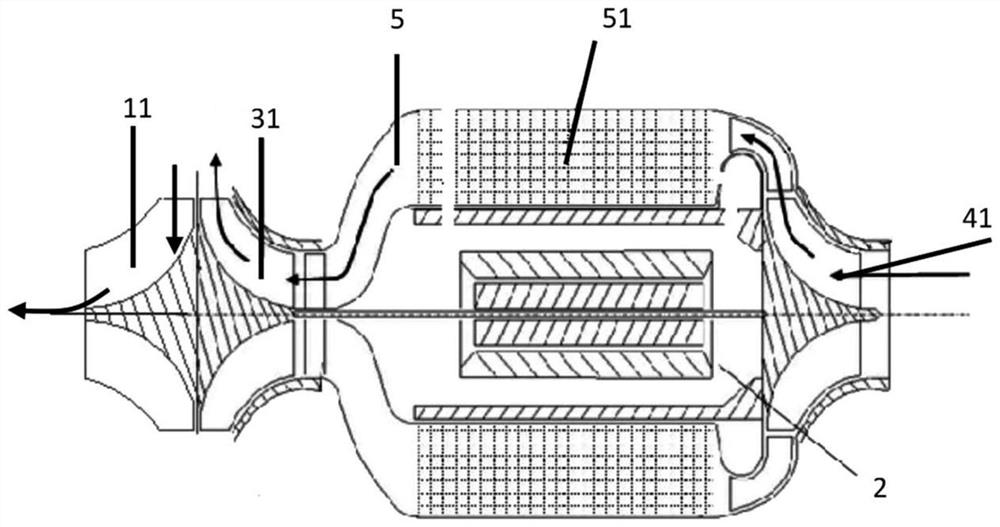
[0029] Such as figure 2 As shown: the high-pressure stage compressor includes a high-pressure impeller 31 and a high-pressure volute 32, and the high-pressure impeller 31 is a radial flow impeller or a mixed flow impeller.

[0030] The low-pressure stage compressor 4 includes a low-pressure impeller 41 and a low-pressure volute 42, the low-pressure impeller 41 is a radial flow impeller or a mixed-flow impeller, and the low-pressure volute is a circumferential annular outlet.

[0031] The motor includes a motor rotor and a stator. The motor shaft is the rotor. The motor shaft is mechanically connected to the high-pressure compressor impeller and the low-pressure compressor impeller. One end of the motor shaft is connect...

Embodiment 2

[0037] Such as figure 1 Shown: a two-stage centrifugal compressor for fuel cells, including a turbine 1, a motor 2, a high-pressure compressor 3, a low-pressure compressor 4, connecting pipelines and a fuel cell stack 6, and the turbine 1 is radial turbine.

[0038] Such as figure 2 As shown: the high-pressure stage compressor includes a high-pressure impeller 31 and a high-pressure volute 32, and the high-pressure impeller 31 is a radial flow impeller or a mixed flow impeller.

[0039] The low-pressure stage compressor 4 includes a low-pressure impeller 41 and a low-pressure volute 42, the low-pressure impeller 41 is a radial flow impeller or a mixed-flow impeller, and the low-pressure volute is a circumferential annular outlet.

[0040] The motor includes a motor rotor and a stator. The motor shaft is the rotor. The motor shaft is mechanically connected to the high-pressure compressor impeller and the low-pressure compressor impeller. One end of the motor shaft is connect...


PUM


Abstract

The invention discloses a two-stage centrifugal compressor for a fuel cell. The compressor comprises a turbine, a motor, a high-pressure-stage gas compressor, a low-pressure-stage gas compressor, a connecting pipeline and a fuel cell stack, one end of a motor main shaft is connected with a high-pressure impeller, the other end of the motor main shaft is connected with a low-pressure impeller, the connecting pipeline is positioned between a gas outlet of the low-pressure-stage gas compressor and a gas inlet of the high-pressure-stage gas compressor, the gas outlet of the high-pressure-stage gas compressor is connected with a cathode gas inlet of the fuel cell stack, a turbine air inlet is connected with a fuel cell stack cathode air outlet, and a turbine and a high-pressure-stage air compressor are machined into a whole. The turbine drives the high-pressure-stage gas compressor to compress sucked air by utilizing waste gas exhausted by combustion of the fuel cell and transmission of a rotating shaft, the power consumption of the high-pressure-stage gas compressor is reduced, the parasitic power of a fuel cell system is reduced, and the output power of the fuel cell is improved; and the back-to-back integrated machining scheme of the turbine impeller and the high-pressure-stage gas compressor impeller is adopted, the size and the weight of the system are reduced, and the purpose that the system is compact is achieved.

Description

technical field [0001] The invention relates to the field of electrically driven air compressors, in particular to a two-stage centrifugal compressor used for fuel cells. Background technique [0002] The hydrogen fuel cell directly outputs electric energy through the chemical reaction between hydrogen and oxygen. The power density of the hydrogen fuel cell is directly related to the air supply pressure and air flow rate of the air supply system. The high air supply pressure and high oxygen partial pressure will accelerate the reaction speed of the fuel cell and output The power increases, and the pressure ratio of the compression system produced by Honeywell abroad can reach 4; the air supply flow rate is large, the raw materials participating in the chemical reaction increase, and the output power increases; the current fuel cell air compression supply system generally directly drives the compressor through the motor compressed air. As the power density requirements of fu...

Claims


Application Information

Patent Timeline
Patent Type & Authority Applications(China)
IPC IPC(8): F04D25/04F04D17/12F04D25/06F04D27/00H01M8/04111
CPCF04D17/12F04D25/04F04D25/0606F04D27/004H01M8/04111Y02E60/50
Inventor 陶林白江涛黄细珍
Owner XECA TURBO TECH (BEIJING) CO LTD
Why Eureka
Try Eureka