
Modularized high-power pulse discharge welding device

A high-power pulse and welding device technology, applied in welding equipment, welding equipment, auxiliary devices, etc., can solve the limitations of research and development and technical application, high-power pulse discharge welding technology is late, and it is difficult to realize the adjustment of discharge current frequency, etc. question

Active Publication Date: 2021-09-10
CHONGQING UNIV
View PDF25 Cites 5 Cited by
  • Summary
  • Abstract
  • Description
  • Claims
  • Application Information

AI Technical Summary

Problems solved by technology

[0003] At present, there are related researches on high-power pulse discharge welding both at home and abroad. Domestic research on high-power pulse discharge welding technology started relatively late, and currently relies on imported equipment Carry out experimental research, but lack of self-developed high-power pulse discharge welding device, which limits related research and development and technology application
[0004]High-power discharge welding involves short-circuit discharge, which requires extremely high requirements for related equipment. The current amplitude of the current high-power pulse discharge welding device is small, which limits its The scope of use, and it is not a modular device, it is difficult to adjust the frequency of the discharge current, and the process of replacing the welding coil is complicated when facing different application scenarios, and the operation is inconvenient. Therefore, in order to solve the above problems, this application proposes a modular high Power pulse discharge welding device

Method used


Image

  • Modularized high-power pulse discharge welding device
  • Modularized high-power pulse discharge welding device
  • Modularized high-power pulse discharge welding device

Examples


Embodiment

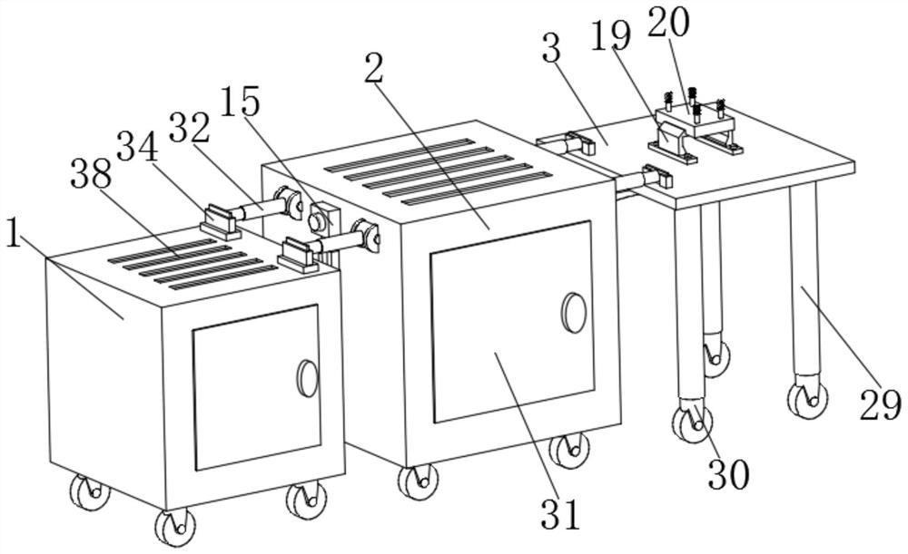
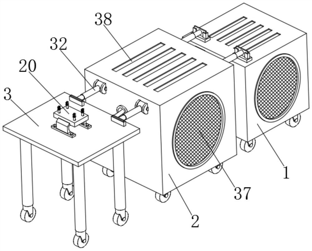
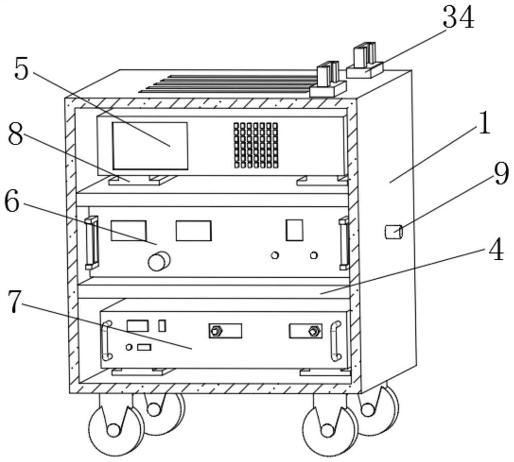
[0040] Example: Reference Figure 1-8 A modular high-power pulse discharge welding device shown includes a power supply box 1, a power storage box 2 arranged on one side of the power supply box 1, a welding platform 3 arranged on one side of the power storage box 2, a power supply box 1, a storage The electric box 2 and the welding platform 3 are respectively installed with a power supply and control module, a power storage-discharge module, and an operation platform module. The power supply and control module includes a control system assembly 5, a trigger source 6, a high-voltage power supply 7, and a power storage-discharge module. It includes multiple energy storage capacitors 11, discharge switches 14, and charging switches 15. The operating platform module includes bus bars 16, welding coils, and coil fixing devices. The same high-voltage silicone wire is installed between the power supply and control module and the energy storage-discharge module. 9. The energy storage ...


PUM


Abstract

The invention discloses a modularized high-power pulse discharge welding device, and relates to the technical field of high-power pulse discharge welding. The modularized high-power pulse discharge welding device comprises a power box, an electricity storage box arranged on one side of the power box, and a welding platform arranged on one side of the electricity storage box; and the power box, the electricity storage box and the welding platform are respectively provided with a power supply and control module, an electricity storage-discharging module and an operation platform module, the power supply and control module comprises a control system assembly, a trigger source and a high-voltage power supply, and the electricity storage-discharging module comprises a plurality of energy storage capacitors, a discharging switch and a charging switch. In the modularized high-power pulse discharge welding device, the control system assembly controls the charging switch to be switched on and switched off, so that the high-voltage power supply charges the energy storage capacitors, when the preset amplitude is reached, charging is stopped, the control system assembly sends a control signal to the trigger source, a multi-rod-electrode vacuum trigger tube is triggered, energy of the energy storage capacitors is released into a welding coil, large pulse current is formed, and welding is achieved.

Description

technical field [0001] The invention relates to the technical field of high-power pulse discharge welding, in particular to a modular high-power pulse discharge welding device. Background technique [0002] High-power pulse discharge welding is one of the applications of pulse power technology in metal processing and forming. It uses pulse discharge to generate pulse high current, and induces electromagnetic force in metal workpieces to make them collide at high speed to form a solid-phase connection. Its main advantages are: it can overcome the difficulty of traditional dissimilar metal welding, there is almost no temperature rise and heat-affected zone, and it can reduce the formation of intermetallic compounds; the energy is controllable, the processing accuracy is high, the repeatability is good, and it is easy to realize industrial automation; safety Environmental protection, no protective gas, no exhaust gas waste. [0003] At present, there are related researches on ...

Claims


Application Information

Patent Timeline
Patent Type & Authority Applications(China)
IPC IPC(8): B23K31/02B23K37/00
CPCB23K31/02B23K37/00B23K37/003Y02P70/10
Inventor 李成祥周言吴浩沈婷
Owner CHONGQING UNIV
Learn More