
Vehicle-mounted carbon dioxide phase change circulating refrigerating system, circulating method and vehicle-mounted refrigerator

A refrigeration system, carbon dioxide technology, applied in gas cycle refrigerators, refrigeration and liquefaction, refrigerators, etc., can solve the problems of small COP value, power and energy occupied by battery life, and limited energy of vehicle battery.

Pending Publication Date: 2021-09-10
上海颐柏企业管理有限公司
View PDF0 Cites 1 Cited by
  • Summary
  • Abstract
  • Description
  • Claims
  • Application Information

AI Technical Summary

Problems solved by technology

[0004] Whether it is a traditional fuel vehicle or a new energy electric vehicle, energy is needed to drive the air conditioning compressor, and the circulating refrigerant in the refrigeration system is used to cool the air. The vehicle air conditioner is powered by the fuel engine or vehicle mounted on the vehicle. It is driven by the electric power of the battery, but due to the limited energy of the fuel engine and the on-board battery, and the COP value of the air conditioning system is relatively small, it takes up a lot of power and energy for battery life

Method used


Image

  • Vehicle-mounted carbon dioxide phase change circulating refrigerating system, circulating method and vehicle-mounted refrigerator
  • Vehicle-mounted carbon dioxide phase change circulating refrigerating system, circulating method and vehicle-mounted refrigerator
  • Vehicle-mounted carbon dioxide phase change circulating refrigerating system, circulating method and vehicle-mounted refrigerator

Examples


Embodiment 1

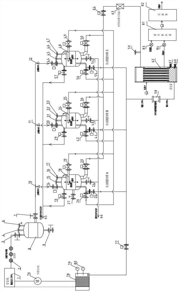
[0103] see figure 1 As shown, this embodiment provides a vehicle-mounted carbon dioxide phase-change cycle refrigeration system, which mainly includes a battery compartment group 78, a vehicle-mounted engine 76, an air compressor 1, and at least two parallel arrangements of liquid CO 2 Storage tank and an evaporator 62.

[0104] read on figure 1 In the vehicle-mounted carbon dioxide phase-change cycle refrigeration system shown, the battery compartment group 78 used is used to provide energy for the vehicle; the vehicle-mounted engine 76 used is used to provide power for the vehicle and the air compressor 1; The press 1 is connected with the vehicle-mounted engine 76 or the battery compartment group 78, and is used to provide high-pressure gas for the system driven by the vehicle-mounted engine 76 or the battery compartment group 78; liquid CO 2 The storage tank can be 2 A and B in parallel, or three A, B and C in parallel, liquid CO 2 The storage tanks are respectively con...

Embodiment 2

[0131] Based on the vehicle-mounted carbon dioxide phase change cycle refrigeration system in embodiment 1, this embodiment provides a carbon dioxide phase change and gas expansion refrigeration, gas pressure change and temperature drop liquefaction cycle refrigeration method, including steps:

[0132] S1, filling the first storage tank A with liquid carbon dioxide that can be used in a single cycle, and filling a small amount of liquid carbon dioxide into the second storage tank B and the third storage tank C;

[0133] S2, the air compressor 1 is driven by the vehicle-mounted engine 76 or the air compressor 1 is directly driven by the battery compartment group 78, and the high-pressure air is fed into the first storage tank A, the second storage tank B and the third storage tank C respectively, and respectively Keep the pressure in the first storage tank A at 25kg / cm 2 , the pressure in the second storage tank B is not lower than 10kg / cm2 , and the pressure in the third stora...

Embodiment 3

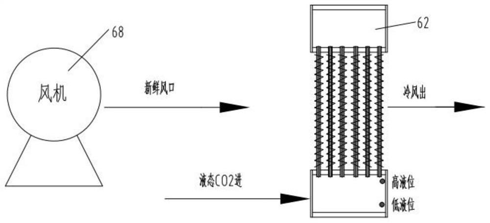
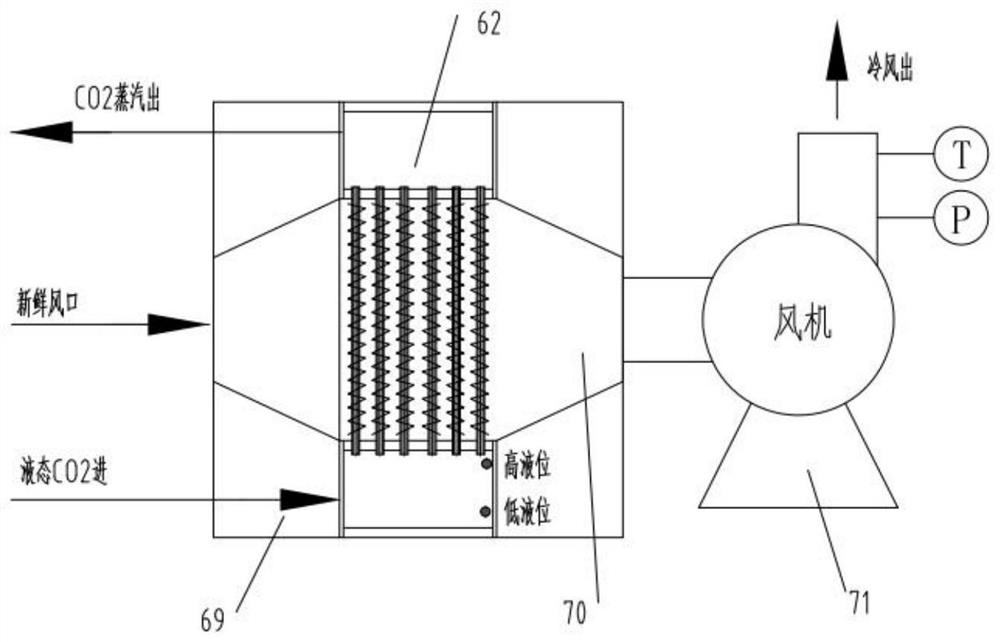
[0144] Such as figure 2 and Figure 5 As shown, different from the above-mentioned embodiment 1, this embodiment provides a vehicle-mounted refrigeration system using the vehicle-mounted carbon dioxide phase-change cycle refrigeration system. The vehicle-mounted refrigeration system also includes a first fresh air blower 68, and the first fresh air blower 68 is arranged At the inlet of the brine of the evaporator 62 , the brine is air, which flows through the outside of the tube wall of the evaporator 62 .

[0145] In this embodiment, the temperature control of the brine at the brine outlet of the evaporator 62 can be achieved by feeding liquid CO 2 High pressure gas control liquid CO from storage tank A / B / C 2 The pressure in tank A / B / C regulates the flow of liquid CO through evaporator 62 2 the quality of. The liquid CO flowing through the evaporator 62 can also be adjusted by a pressure reducing valve or a flow meter 58. 2 the quality of. It is also possible to contro...


PUM


Abstract

The invention discloses a vehicle-mounted carbon dioxide phase change circulating refrigerating system, a circulating method and a vehicle-mounted refrigerator. The refrigerating system involves a battery bin group, a vehicle-mounted engine, an air compressor, at least two liquid CO2 storage tanks arranged in parallel and an evaporator, wherein the liquid CO2 storage tanks are connected with the air compressor; and the evaporator is connected with the liquid CO2 storage tanks so as to alternately receive a liquid CO2 refrigerant provided by the liquid CO2 storage tanks and gasify the liquid CO2 refrigerant in the evaporator, and heat exchange is carried out through sensible heat released by cooling of a secondary refrigerant flowing through the outer surface of the pipe wall of the evaporator. According to the vehicle-mounted carbon dioxide phase change circulating refrigerating system, the liquid CO2 refrigerant reverse circulation principle is used for refrigeration, the liquid CO2 refrigerant is fed into the evaporator through high-pressure air in a pressed mode to be gasified into steam, latent heat needs to be absorbed in the gasification process, the absorbed latent heat comes from the sensible heat released by cooling of cold-carrying fresh air flowing through the surface of the evaporator, and after the cold-carrying fresh air releases the sensible heat, the temperature is reduced to achieve the vehicle-mounted refrigeration process.

Description

technical field [0001] The invention relates to the technical field of air conditioning and refrigeration, in particular to a vehicle-mounted carbon dioxide phase-change cycle refrigeration system, a cycle method, and a vehicle-mounted refrigerator. Background technique [0002] As we all know, the vehicle-mounted air-conditioning system is a device that cools, heats, ventilates, and purifies the air in the vehicle compartment. It can provide a comfortable environment for passengers, reduce driver fatigue, and improve driving safety. Existing vehicle-mounted refrigeration technology widely utilizes the vaporization process of refrigerant (liquid) at low pressure to produce cooling capacity. The refrigeration methods using this principle can be divided into vapor compression cycle refrigeration, absorption refrigeration and steam injection refrigeration. What the refrigeration process needs is a process in which the refrigerant can be recycled. The refrigerant absorbs heat an...

Claims


Application Information

Patent Timeline
Patent Type & Authority Applications(China)
IPC IPC(8): F25B9/00F25B9/08F25B41/20B60H1/00
CPCF25B9/008F25B9/08B60H1/00321F25B2309/06
Inventor 杨景峰
Owner 上海颐柏企业管理有限公司
Learn More