Method for judging machinability of aircraft component compensation layer

A technology for aircraft parts and compensation layers, applied in sustainable transportation, instruments, geometric CAD, etc., can solve problems such as insufficient machinability judgment methods, low efficiency, and slingshots.

Active Publication Date: 2021-09-10
CHENGDU AIRCRAFT INDUSTRY GROUP
View PDF5 Cites 2 Cited by
  • Summary
  • Abstract
  • Description
  • Claims
  • Application Information

AI Technical Summary

Problems solved by technology

[0006] The purpose of the present invention is to solve the problem of "insufficient method for judging the machinability of the compensation layer bonded to the edge strip surface of the component, which leads to blindly increasing the rigidity and resistance of the edge strip surface of the component during the processing process, resulting in low efficiency, or the occurrence of snapping knives." , debonding a...

Method used


Image

  • Method for judging machinability of aircraft component compensation layer
  • Method for judging machinability of aircraft component compensation layer
  • Method for judging machinability of aircraft component compensation layer

Examples


Embodiment 1

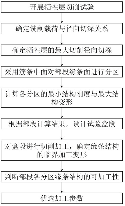
[0069] This embodiment discloses a method for judging the machinability of an aircraft component compensation layer, as a basic implementation of the present invention, such as figure 1 shown, including the following steps:

[0070] S1, design the cutting test, obtain the law between the cutting load and the cutting parameters through the cutting test, and determine the limit cutting parameters;

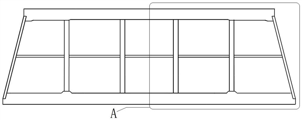
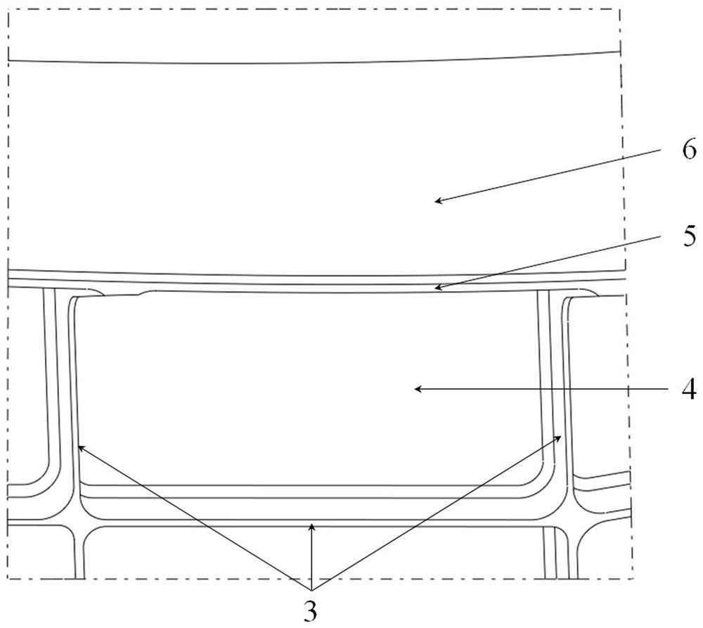
[0071] S2, combined with the structural characteristics of the section (the section structure is left-right symmetrical, bounded by the mid-plane of the web of the rib, frame and beam, and the edge of the edge), the processing surface of the compensation layer liner is divided to form Section processing area, such as Figure 6 and Figure 7 As shown, it is divided into 83 section processing areas, Figure 7 (1-1)~(1-83) in each represent a section processing area, and each section processing area has a relative stiffness minimum point ( Figure 8 As shown, the edge of the compe...

Embodiment 2

[0086] This example discloses a method for judging the machinability of an aircraft component compensation layer. As a preferred embodiment of the present invention, that is, in Example 1, the cutting test in step S1 is to select EW100 fiberglass composite material as the compensation layer lining Pad, carry out mechanical performance test, and calibrate the cutting mechanical performance of compensation layer pad, including the following steps:

[0087] S1-1, bonding a 2mm thick compensation layer liner on the aluminum alloy plate;

[0088] S1-2, the bottom of the aluminum alloy plate is connected to the dynamometer, and the dynamometer is directly below the pad of the compensation layer, such as Figure 5 shown;

[0089] S1-3, based on the numerical control system of the machine tool, set the processing parameters for the compensation layer liner. Among the processing parameters, the radial depth of cut ; Preferably, the cutting tool used by the machine tool for processin...

Embodiment 3

[0096] This example discloses a method for judging the machinability of an aircraft component compensation layer. As a preferred embodiment of the present invention, that is, in Example 2, the limit cutting parameter in step S1 is the maximum machinable value of the compensation layer liner. radial depth of cut , and the maximum radial depth of cut is based on the bond-peel strength of the compensation liner To determine the bond-peel strength of the compensation layer liner Including the tear-off strength between the FRP composite material and the glue and the tear-off strength between the aluminum alloy plate and the glue is , then the maximum radial depth of cut The determination includes the following steps:

[0097] S1-6, based on , combined with of axis, axis and range of axis orientations, obtain the formula and , then during the cutting process, the tangential cutting load borne by the compensation layer liner ;

[0098] S1-7, order and ...


PUM


Abstract

The invention belongs to the technical field of aircraft component assembly, and particularly relates to a method for judging the machinability of an aircraft component compensation layer, which comprises the following steps of: obtaining a rule between a cutting load and a cutting parameter through a cutting test, and determining a limit cutting parameter; combining the structural characteristics of the section, partitioning the processing surface of the compensation layer, and calculating to obtain the deformation of all relative stiffness minimum points on the section and the minimum structural stiffness; designing a box section test piece according to requirements, performing partitioning according to box section structural characteristics, and obtaining deformation of all relative rigidity minimum points on a box section and the minimum structural rigidity through calculation; and determining critical machining deformation, and judging the machinability of the section compensation layer on the basis of the critical machining deformation in combination with rules among the parameters, so that optimization of the cutting parameters of all the partitions is achieved. According to the method, a process calculation and analysis method is provided for machinability judgment of the section compensation layer liner, the problems of machining vibration and debonding in the machining process can be predicted, and parts which cannot be machined can be accurately positioned.

Description

technical field [0001] The invention belongs to the technical field of aircraft component assembly, in particular to a method for judging the machinability of compensation layers of aircraft components. Background technique [0002] When developing a new type of aircraft, in order to ensure the stealth performance of the aircraft, improve the shape accuracy and interchangeability of the aircraft components; after the skeleton assembly of the aircraft components is completed (such as figure 2 shown), a compensation layer needs to be bonded on the edge of the frame (such as image 3 As shown), the shape accuracy of the skeleton is guaranteed by CNC cutting the compensation layer. The component skeleton is composed of frames, beams and other structures, and the structure of the area to be processed is ribs, web surfaces, edge strips, and compensation layers (such as Figure 4 shown). [0003] The edge strip of the segmental skeleton structure is a thin-walled structure, the ...

Claims


Application Information

Patent Timeline
IPC IPC(8): G06F30/15G06F30/17G06F30/20G06F111/10G06F119/14
CPCG06F30/15G06F30/17G06F30/20G06F2111/10G06F2119/14Y02T90/00
Inventor 陈雪梅舒阳叶翔宇陈清良骆金威益建朋潘雨勾江洋
Owner CHENGDU AIRCRAFT INDUSTRY GROUP
Why Eureka
Try Eureka