Silicon-based negative electrode material for inhibiting crack formation in lithium intercalation and deintercalation process and preparation method of silicon-based negative electrode material

A silicon-based negative electrode material, silicon-based material technology, applied in the direction of negative electrode, battery electrode, active material electrode, etc., can solve the problems of poor structural stability and poor structural stability of ternary materials, and achieve the advantages of lithium intercalation and delithiation, The effect of improving conductivity and avoiding direct contact

Inactive Publication Date: 2021-09-14
BEIJING IAMETAL NEW ENERGY TECH CO LTD
View PDF9 Cites 4 Cited by
  • Summary
  • Abstract
  • Description
  • Claims
  • Application Information

AI Technical Summary

Problems solved by technology

[0006] During the cycle of ternary materials, due to the accumulation of stress, cracks will be generated inside the secondary particles, resulting in poor structural stability of ternary materials. Doping technology is an important method to solve the poor structural stability of ternary materials.
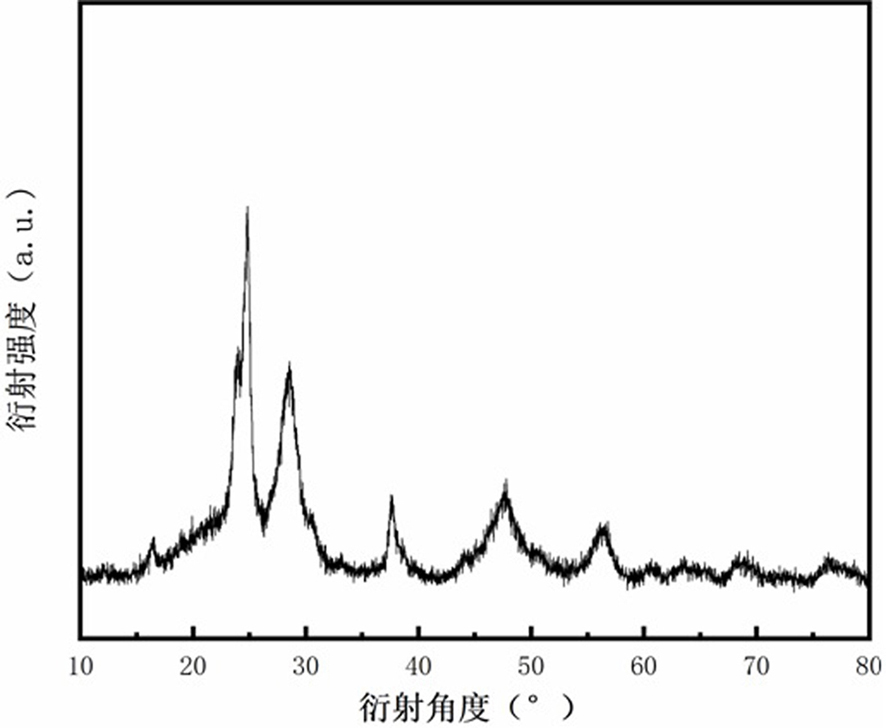
Based on the problem of cracks existing in the charging and discharging process of silicon-based negative electrode materials in the background technology, the present invention proposes a silicon-based negative electrode material that suppresses crack formation during lithium intercalation and desorption and a preparation method thereof, and relieves silicon-based negative electrode materials through element doping protection. The internal stress of the negative electrode material, with the help of the perovskite coating layer and the carbon coating layer, jointly inhibits the formation of cracks during the lithium insertion and extraction process, thereby improving the cycle life of the material

Method used

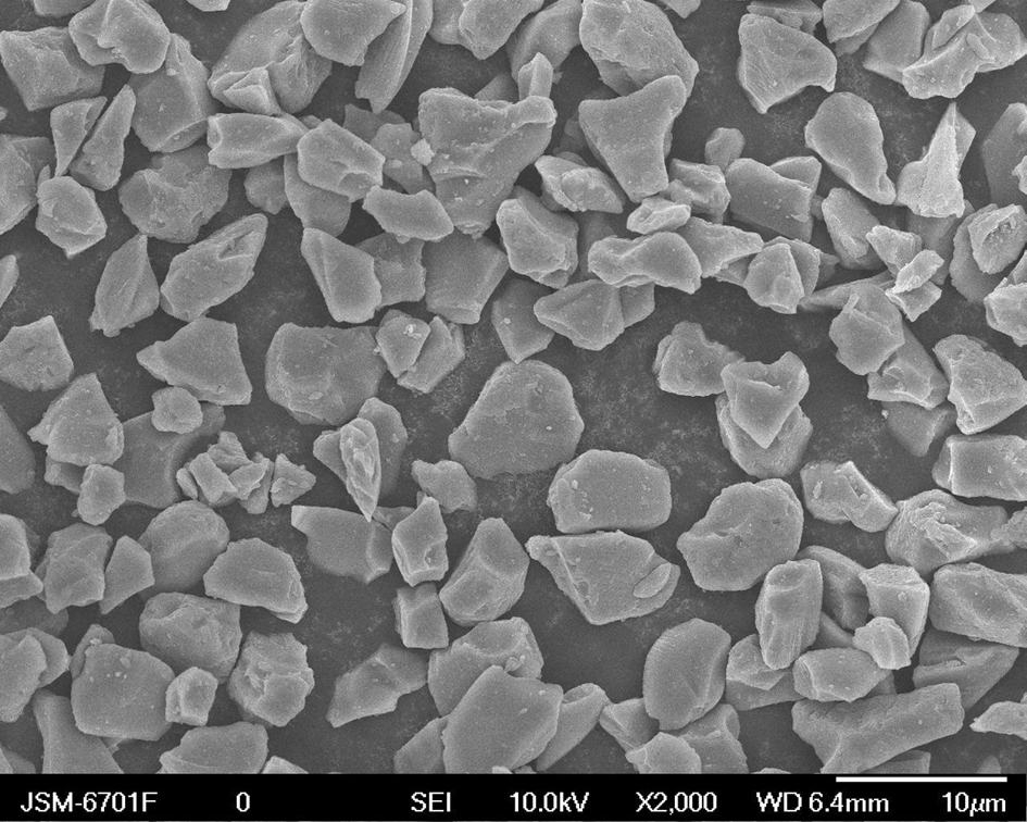
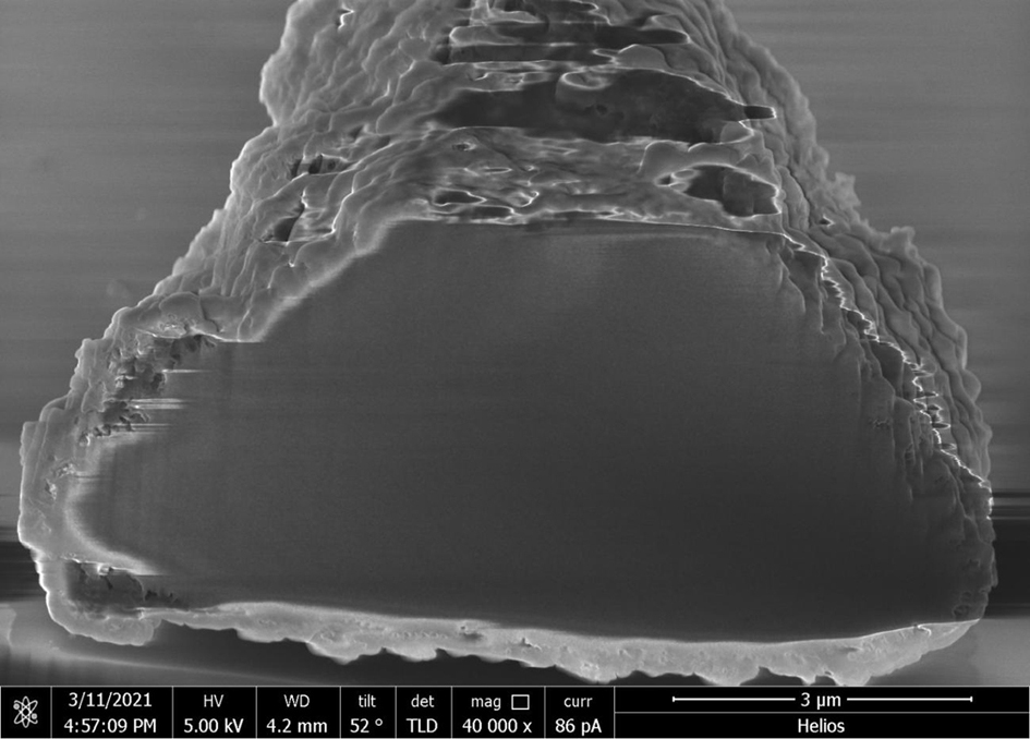

Image

  • Silicon-based negative electrode material for inhibiting crack formation in lithium intercalation and deintercalation process and preparation method of silicon-based negative electrode material
  • Silicon-based negative electrode material for inhibiting crack formation in lithium intercalation and deintercalation process and preparation method of silicon-based negative electrode material
  • Silicon-based negative electrode material for inhibiting crack formation in lithium intercalation and deintercalation process and preparation method of silicon-based negative electrode material

Examples


Embodiment 1

[0051] (1) Accurately weigh 10g of silicon oxide material (with a particle size of about 5µm) and 1g of lithium borohydride into a ball mill for mixed ball milling. The speed of the mixed ball mill is 550rpm, and the milling time is 7h.

[0052] (2) After the mixture obtained in step (1) is ball milled and mixed evenly, the mixed material is placed in a tube furnace for sintering under the protection of argon (gas flow rate is 150mL / min), and the heating rate is 5°C / min Raise the temperature to 650°C, keep it warm for 7 hours, and grind it thoroughly after cooling.

[0053] (3) According to LaCoO 3 Stoichiometric ratio, preparation of a perovskite precursor solution with a total metal concentration of 0.1M: dissolving lanthanum nitrate and cobalt nitrate in deionized water and ethanol (volume ratio 1:1) to obtain a mixed solution, and then adding urea to the solution to obtain Precursor solution, in which the molar ratio of urea to metal cation is 20:1, urea makes the precurs...

Embodiment 2

[0057] The boron-doped silicon-based negative electrode material was prepared according to the same method as in Example 1, except that in step (1), 15 g of silicon oxide material (with a particle size of about 5 μm) and 1 g of boron oxide were weighed and added to a ball mill Mixing ball milling is carried out, the rotation speed of the mixing ball milling is 500 rpm, and the time of ball milling is 5 hours. The thickness of the perovskite coating layer in the silicon-based negative electrode material is about 140-150 nm.

Embodiment 3

[0059] (1) Accurately weigh 10g of silica material (with a particle size of about 5µm) and 1g of aluminum nitrate into a ball mill for mixed ball milling. The speed of the mixed ball mill is 550rpm, and the milling time is 7h.

[0060] (2) After ball milling and mixing evenly, put the mixed material into a tube furnace for sintering under the protection of argon (gas flow rate of 150mL / min), raise the temperature to 650°C at a heating rate of 5°C / min, and keep it warm. 7h, fully ground after cooling.

[0061] (3) According to LaCoO 3 Stoichiometric ratio, prepare a perovskite precursor solution with a total metal concentration of 0.1M: dissolve lanthanum nitrate and cobalt nitrate in deionized water and ethanol (volume ratio 1:1) to obtain a mixed solution, and then add urea to the solution Obtain the precursor solution, in which the molar ratio of urea to metal cation is 20:1, urea makes the precursor evenly distributed and promotes the formation of the required perovskite p...


PUM

PropertyMeasurementUnit
thicknessaaaaaaaaaa
thicknessaaaaaaaaaa
particle sizeaaaaaaaaaa

Abstract

The invention discloses a silicon-based negative electrode material for inhibiting crack formation in a lithium intercalation and deintercalation process and a preparation method of the silicon-based negative electrode material, the silicon-based negative electrode material is of a three-layer composite structure which sequentially comprises a silicon-based material layer, a perovskite coating layer and an amorphous carbon coating layer from inside to outside; the silicon-based material layer is doped with at least one element selected from B, P, Al, Zr, Ti and Mg; and the perovskite is LaMO3, and M = Co and / or Fe. According to the invention, the method of high-temperature sintering element doping, perovskite coating layer coating and carbon coating is adopted to inhibit the formation of cracks in the lithium intercalation and deintercalation process of the silicon-based negative electrode material, so that the huge stress change of the silicon-based negative electrode material in the lithium intercalation and deintercalation process is effectively relieved, and the formation of cracks in particles is inhibited; and relatively high first coulombic efficiency and excellent cycling stability are shown.

Description

technical field [0001] The invention relates to the technical field of designing lithium-ion battery materials, in particular to a silicon-based negative electrode material and a preparation method thereof that suppress crack formation during lithium intercalation and extraction. Background technique [0002] With the development of lithium-ion batteries to large-scale applications such as electric vehicles and renewable energy storage systems, people's demands on the performance of lithium-ion batteries are also increasing, and performance indicators such as energy density and power density of primary lithium-ion batteries need to be further improved. In terms of negative electrode materials, traditional graphite carbon negative electrode materials have limited specific capacity, which has been difficult to meet the needs of high energy density batteries. At present, the anode materials with high energy density that are mainly developed commercially are mainly silicon-based...

Claims


Application Information

Patent Timeline
Patent Type & Authority Applications(China)
IPC IPC(8): H01M4/36H01M4/48H01M4/62H01M10/0525
CPCH01M4/366H01M4/483H01M4/628H01M4/625H01M10/0525H01M2004/021H01M2004/027Y02E60/10
Inventor 程晓彦李晓东闫明妍李金熠岳风树
Owner BEIJING IAMETAL NEW ENERGY TECH CO LTD
Why Eureka
Try Eureka