
Energy power system of solar unmanned aerial vehicle

A technology for unmanned aerial vehicles and power systems, applied in the field of energy power systems for solar unmanned aerial vehicles, can solve the problems of reduced overall system efficiency, reduced transmission efficiency, increased weight, etc., to reduce scale and space distribution, reduce wire usage, The effect of improving energy efficiency

Inactive Publication Date: 2021-09-17
CHINA ELECTRONIC TECH GRP CORP NO 18 RES INST +1
View PDF3 Cites 0 Cited by
  • Summary
  • Abstract
  • Description
  • Claims
  • Application Information

AI Technical Summary

Problems solved by technology

Insufficient power supply capacity of energy storage batteries, insufficient ability to cope with changeable conditions, and failure to generate power in consideration of safety margins are the main problems currently restricting the system from running day and night for more than 30 days
The reduction in transmission efficiency caused by the scale effect of the aircraft (100-meter scale) and the difference in power generation capacity at different locations increase the possibility of inconsistent energy storage batteries, further limiting the role of energy storage batteries
Although the power supply and distribution system is self-stabilizing under ideal conditions, the limited boundary conditions and too many random interference factors during high-altitude flight have destroyed the self-stabilizing characteristics of the system. In the absence of suitable control strategy management, it is easy to The accumulation of small problems eventually causes the system to gradually lose control
[0003] Traditional centralized or distributed energy systems treat power generation, energy storage, and loads as independent links, and place too much emphasis on the independence of each link, making it difficult for the energy system to fully utilize the characteristics of each link and give full play to their respective advantages, eventually leading to system failure. Reduced overall efficiency and increased weight
More importantly, the design of traditional centralized or distributed energy systems cannot solve the many contradictions between it and the high-efficiency and long-term voyage requirements of solar-powered unmanned aerial vehicles, such as the contradiction between nighttime energy demand and insufficient discharge capacity of energy storage batteries. The contradiction between the scale layout structure and efficient energy transmission and balanced power generation demand, the contradiction between the diversification of load power demand and the single power supply system, and the contradiction between the stable power supply demand and the unpredictable long-term use environment
In addition, the traditional aircraft energy system design adopts a mutually isolated multi-bus power supply system, which leads to the fragmentation of the layout of the aircraft energy system, and does not use the later upgrade and maintenance of equipment
[0004] The power system, flight control system, and payload system have different requirements for power supply energy, power supply quality, and dynamic response. It is difficult for a single busbar structure to meet the diverse power supply requirements of loads, resulting in an excessive number of converters and precise control of busbar voltage. The loss outweighs the gain

Method used


Image

  • Energy power system of solar unmanned aerial vehicle
  • Energy power system of solar unmanned aerial vehicle
  • Energy power system of solar unmanned aerial vehicle

Examples


Embodiment Construction

[0034] In order to make the object, technical solution and advantages of the present invention clearer, the present invention will be further described in detail below in combination with specific embodiments and with reference to the accompanying drawings. It should be understood that these descriptions are exemplary only, and are not intended to limit the scope of the present invention. Also, in the following description, descriptions of well-known structures and techniques are omitted to avoid unnecessarily obscuring the concept of the present invention.

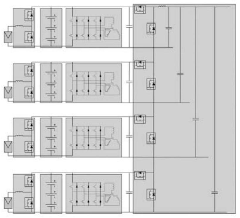
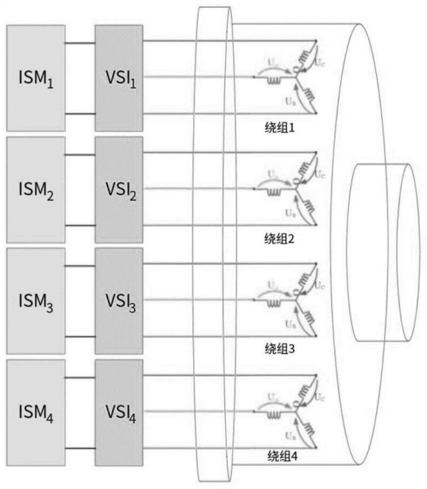
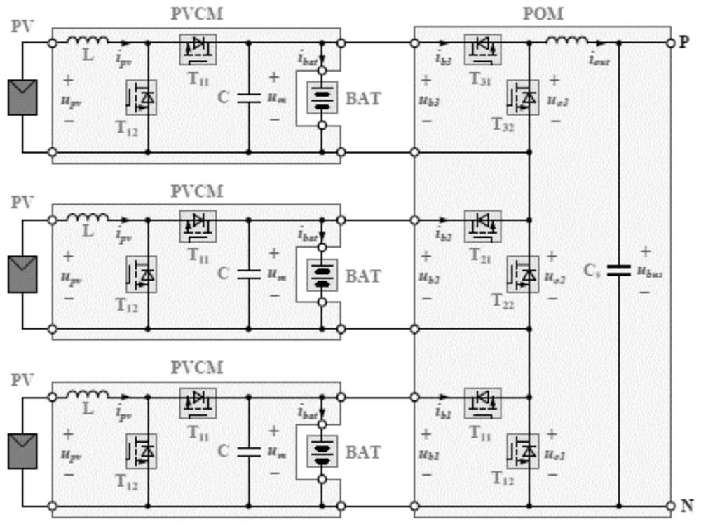
[0035] Such as Figure 1-13 , in the embodiment of the present application, the present invention provides a solar unmanned aerial vehicle energy power system, including:

[0036] A networked DC microgrid system for providing electrical energy;

[0037] Coaxial modular motor for kinetic energy;

[0038] The power conversion unit is used to convert the electric energy of the networked DC microgrid system and supply powe...


PUM


Abstract

An energy power system of a solar unmanned aerial vehicle comprises a networked direct current micro-grid system used for providing electric energy; a coaxial modular motor is used for providing kinetic energy; a power conversion unit is used for converting the electric energy of the networked direct-current micro-grid system and supplying power to the coaxial modular motor; and the power conversion unit is respectively connected with the networked direct current micro-grid system and the coaxial modular motor. According to the multi-bus structure and the power system structure based on the motor sub-module, the use amount of the DC / DC converter is effectively reduced, the weight is reduced, the low-voltage configuration is easy to configure power output of different voltage levels by properly selecting a parallel connection form of a plurality of sub-systems, the transformation ratio of the DC / DC converter is effectively reduced, and the energy efficiency is improved. The subsystems are in a peer-to-peer relationship, are relatively independent and are flexible in design. Meanwhile, the modules are backups for each other, the redundancy is increased, the system can still work when part of nodes fail, and the reliability is improved.

Description

technical field [0001] The invention belongs to the technical field of unmanned aircraft energy power systems, and in particular relates to a solar energy power system for unmanned aircraft. Background technique [0002] The energy power system is the "heart" of a solar unmanned aerial vehicle, and it is the basis for ensuring the efficient operation of the aircraft and giving full play to its functions. Therefore, the performance of the energy power system determines whether a certain type of unmanned aerial vehicle is feasible and reliable for a long time. a key factor. The energy source of the solar unmanned aerial vehicle during the day is solar energy, and the energy source at night is the energy stored by the energy storage battery during the day. Insufficient power supply capacity of energy storage batteries, insufficient ability to cope with changing conditions, and failure to generate power when considering safety margins are the main problems currently restricting...

Claims


Application Information

Patent Timeline
Patent Type & Authority Applications(China)
IPC IPC(8): H02J1/10H02J1/14H02J7/35H02P25/02H02P25/22H02P27/00H02P25/022H02P21/00H02P21/22
CPCH02J1/10H02J1/14H02J7/35H02P25/02H02P25/22H02P27/00H02P25/022H02P21/0003H02P21/22H02J2300/24H02J2300/26H02P2207/05Y02E10/56
Inventor 孙子路吕冬翔仇海波钟豪李钊
Owner CHINA ELECTRONIC TECH GRP CORP NO 18 RES INST
Learn More