Catalytic membrane coupling system and application method thereof

A technology of coupling system and application method, applied in the field of membrane separation sewage treatment, can solve the problems of low photocatalyst quantum efficiency, base film damage, low light utilization rate, etc., so as to reduce transportation and storage costs, improve cleaning efficiency, and improve light The effect of catalytic efficiency

Active Publication Date: 2021-09-24
INST OF PROCESS ENG CHINESE ACAD OF SCI +1
View PDF12 Cites 0 Cited by
  • Summary
  • Abstract
  • Description
  • Claims
  • Application Information

AI Technical Summary

Problems solved by technology

Moreover, the system can design the surface of the photocatalytic membrane and its component form without affecting the performance of the separation membrane, which solves the problems of low light utilization rate, low photocatalyst quantum efficiency, The basement membrane is easy to cause damage, and has a good prospect for industrial application

Method used


Image

  • Catalytic membrane coupling system and application method thereof

Examples


Embodiment 1

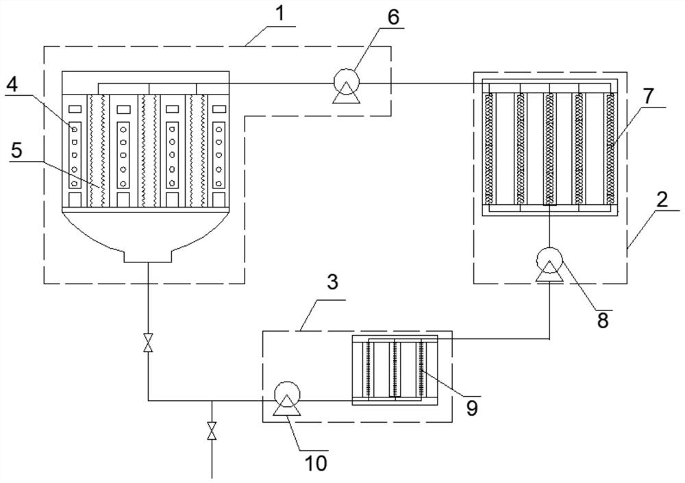
[0065] This embodiment provides a catalytic membrane coupling system, the structural schematic diagram of the system is as follows figure 1 As shown, the system includes a photocatalytic membrane unit 1 , a self-cleaning membrane unit 2 and a water regeneration unit 3 which are sequentially connected in a cycle.

[0066] The photocatalytic membrane unit 1 is provided with 4 groups of light source generating equipment 4, and a photocatalytic membrane assembly 5 is arranged between each two groups of the light source generating equipment 4, and also includes a peroxidizer connected to the photocatalytic membrane assembly 5. Hydrogen delivery device 6; The photocatalytic membrane module 5 is a flat membrane module; The light source generating device 4 is a full-band light source generating device 4; The photocatalytic film used in the photocatalytic membrane module 5 includes the first base film and Titanium dioxide loaded on the first base film, the first base film is a ceramic ...

Embodiment 2

[0070] This embodiment provides a catalytic membrane coupling system, which includes a photocatalytic membrane unit 1 , a self-cleaning membrane unit 2 and a water regeneration unit 3 which are sequentially connected in a cycle.

[0071] The photocatalytic membrane unit 1 is provided with 5 groups of light source generating equipment 4, and a photocatalytic membrane assembly 5 is arranged between each two groups of the light source generating equipment 4, and also includes a peroxidizer connected to the photocatalytic membrane assembly 5. Hydrogen delivery device 6; the photocatalytic membrane module 5 is a tubular membrane module; the light source generating device 4 is a full-band light source generating device 4; the photocatalytic film used in the photocatalytic membrane module 5 includes a first base film and a carbon nitride nanocatalyst loaded on the first base film, the first base film is a ceramic membrane DEA100 with a pore size of 0.22 μm.

[0072] The self-cleaning...

Embodiment 3

[0075] This embodiment provides a catalytic membrane coupling system, which includes a photocatalytic membrane unit 1 , a self-cleaning membrane unit 2 and a water regeneration unit 3 which are sequentially connected in a cycle.

[0076] The photocatalytic membrane unit 1 is provided with 3 groups of light source generating equipment 4, and a photocatalytic membrane assembly 5 is arranged between each two groups of the light source generating equipment 4, and also includes a peroxidizer connected to the photocatalytic membrane assembly 5. Hydrogen delivery device 6; The photocatalytic membrane module 5 is a hollow fiber membrane module; The light source generating device 4 is an ultraviolet light generating device; The photocatalytic membrane used in the photocatalytic membrane module 5 includes a first base film and a load Zinc oxide on the first base film, the first base film is a ceramic film DEB100 with a pore size of 5 μm.

[0077] The self-cleaning membrane unit 2 includ...


PUM

PropertyMeasurementUnit
pore sizeaaaaaaaaaa
molecular weightaaaaaaaaaa
pore sizeaaaaaaaaaa

Abstract

The invention provides a catalytic membrane coupling system and an application method thereof. The catalytic membrane coupling system comprises a photocatalytic membrane unit, a self-cleaning membrane unit and a water regeneration unit which are sequentially and circularly connected, wherein the photocatalytic membrane unit is provided with at least two groups of light source generation equipment, and a photocatalytic membrane assembly is arranged between every two groups of light source generation equipment; the self-cleaning membrane unit comprises a Fenton-like catalytic membrane assembly; and the water regeneration unit comprises a nanofiltration membrane assembly. According to the system, a hydrogen peroxide oxidizing agent is generated through photocatalysis and then conveyed to the self-cleaning membrane unit to be used for membrane pollution cleaning and degradation of small molecular organic matter in water, so that a separation membrane continuously, effectively and stably runs, the pollution resistance of the membrane is improved, the service life of the membrane is prolonged, and the industrial application prospect is excellent.

Description

technical field [0001] The invention belongs to the technical field of membrane separation sewage treatment, and in particular relates to a catalytic membrane coupling system and an application method thereof. Background technique [0002] Membrane technology has been widely used in industrial organic wastewater and municipal sewage treatment due to its advantages such as simple equipment, low energy consumption, and no secondary pollution. However, the low selectivity of membrane separation and serious membrane fouling are two main problems in the application process, which restrict the development of membrane technology. First of all, in the wastewater treatment process, in order to ensure the penetration of inorganic salts, the interception effect of small molecule organic matter is not high. In addition, membrane fouling is an inevitable problem in the membrane process, which is caused by the interaction between the membrane material and various pollutants, which will a...

Claims


Application Information

Patent Timeline
Patent Type & Authority Applications(China)
IPC IPC(8): B01D65/02C02F1/44C02F9/04C02F101/30
CPCB01D65/02C02F1/44C02F1/442C02F1/66C02F2101/30C02F2303/16B01D2321/168
Inventor 罗建泉张慧如万印华陈楚龙
Owner INST OF PROCESS ENG CHINESE ACAD OF SCI
Why Eureka
Try Eureka