
TMR stirrer material contact surface treatment process

A treatment process and contact surface technology, applied in the direction of mixer accessories, mixers, anti-corrosion coatings, etc., can solve the problems of easy-to-corrosion TMR mixers, poor wear resistance of coatings, and easy to pollute feed, etc., to reduce friction coefficient and enhance durability Wear corrosion resistance, good cleaning effect

Inactive Publication Date: 2021-09-28
SHANGHAI CHEUNGHUNG AGRI HUSBANDRY MECHANICAL EQUIP
View PDF7 Cites 0 Cited by
  • Summary
  • Abstract
  • Description
  • Claims
  • Application Information

AI Technical Summary

Problems solved by technology

[0004] Through the related technologies mentioned above, although the material contact surface of the TMR mixer has strong corrosion resistance, the wear resistance of the coating is poor. When the TMR mixer is used for a long time, the coating is prone to fall off. On the one hand The coating is mixed with the feed, which is easy to pollute the feed; on the other hand, after the coating falls off, some corrosive materials in the feed are easy to corrode the TMR mixer

Method used


Image

  • TMR stirrer material contact surface treatment process
  • TMR stirrer material contact surface treatment process
  • TMR stirrer material contact surface treatment process

Examples


Embodiment 1

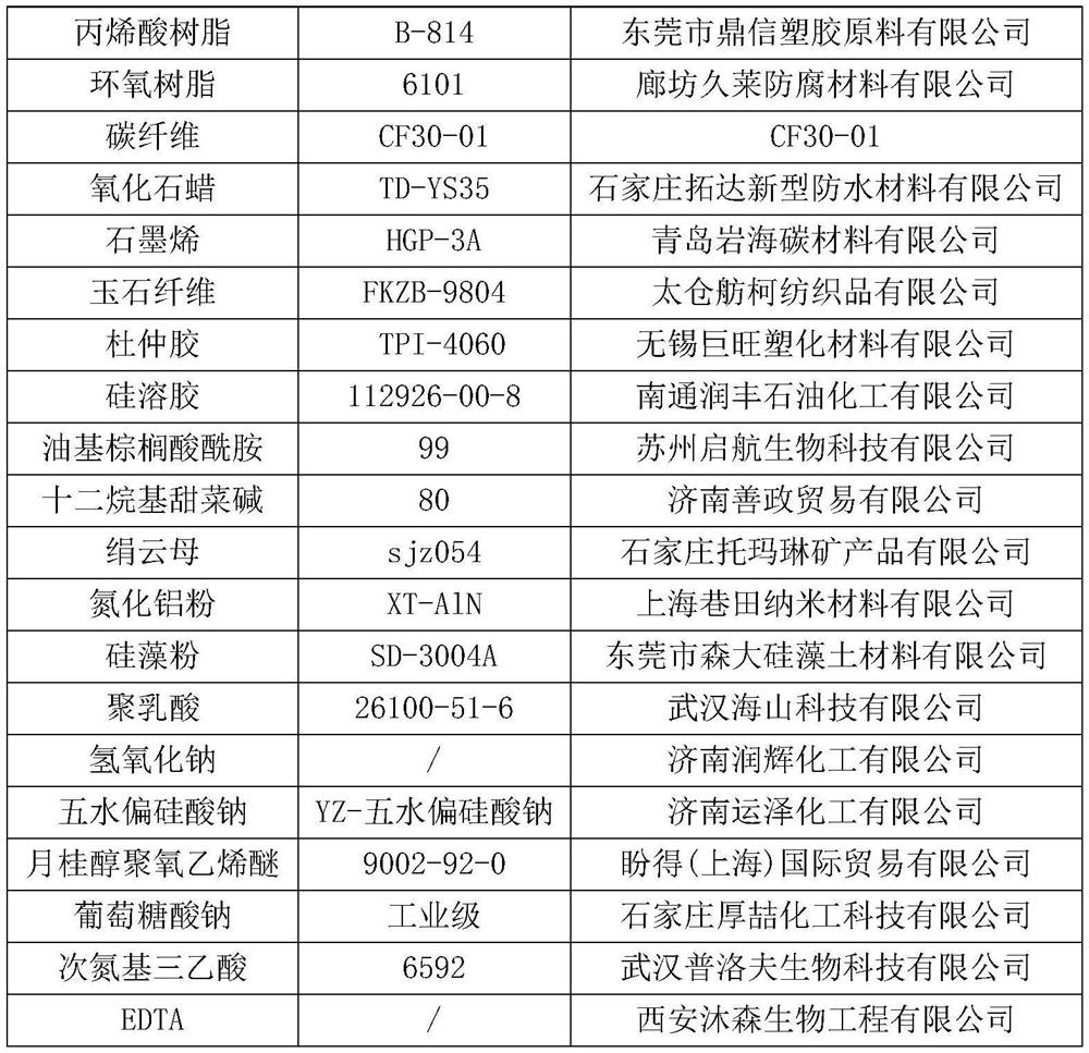
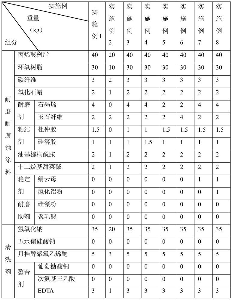
[0059] A kind of TMR mixer material contact surface treatment process, the concrete component that comprises and weight are as shown in table 2, are made by following steps:

[0060] S1: Preparation of cleaning agent: Mix and stir sodium hydroxide, polyoxyethylene lauryl ether, chelating agent and deionized water at a stirring speed of 1000r / min, and obtain a cleaning agent after stirring evenly;

[0061] Preparation of wear-resistant and corrosion-resistant coatings: Mix and stir acrylic resin and epoxy resin at a stirring speed of 1200r / min. After stirring evenly, the first mixture is obtained; mix the first mixture with oxidized paraffin wax, oleyl palmitic acid amide, dodecane The base betaine is mixed and stirred, and the stirring speed is 1000r / min, and the second mixture is obtained after stirring evenly; the second mixture is mixed and stirred with the wear-resistant agent and the binder, and the stirring speed is 1000r / min, and the stirring is uniform and then left sta...

Embodiment 2

[0065] Embodiment 2: a kind of TMR mixer material contact surface treatment process, the difference with embodiment 1 is that the components and weight of cleaning agent and wear-resistant and corrosion-resistant coating are different, and the included concrete components and weight are as shown in table 2 .

Embodiment 3-4

[0066] Embodiment 3-4: a kind of TMR mixer material contact surface treatment process, the difference with embodiment 1 is that the components and weight of the binder are different, and the specific components and weight included are as shown in table 2.


PUM


Abstract

The invention relates to the technical field of stirrers, and particularly discloses a TMR stirrer material contact surface treatment process which comprises the following steps: cleaning a TMR stirrer material contact surface by adopting a cleaning agent, then washing the TMR stirrer material contact surface by adopting water, and drying the TMR stirrer material contact surface after washing the TMR stirrer material contact surface for 2-4 times; evenly coating the TMR stirrer material contact surface with a wear-resistant and corrosion-resistant coating, adopting hot air for curing, controlling the temperature of the hot air to range from 130 DEG C to 150 DEG C, and the time to range from 10 min to 20 min; and conducting cooling at the temperature of 25-35 DEG C to form a film. The wear-resistant and corrosion-resistant coating comprises the following raw materials in parts by weight: 20-40 parts of acrylic resin, 10-30 parts of epoxy resin, 2-3 parts of carbon fibers, 1-2 parts of oxidized paraffin, 2-6 parts of a wear-resistant agent, 1-2.5 parts of a binder, 1-2 parts of oil-based palmitic acid amide and 1-2 parts of dodecyl betaine; and the wear-resistant agent comprises at least one of graphene and jade fiber. The TMR stirrer material contact surface treated by the process has the advantage of good wear resistance.

Description

technical field [0001] The present application relates to the technical field of mixers, in particular to a material contact surface treatment process of a TMR mixer. Background technique [0002] TMR Feed Mixer is a new type of equipment that mixes cut roughage, concentrated feed and trace elements and other additives according to the nutritional needs of dairy cows and other livestock at different feed stages, which can reduce labor intensity of artificial feeding, save feeding costs and improve economic efficiency. [0003] When the TMR mixer is mixing feed and other materials, the contact surface between the TMR mixer and the material mainly includes the inner wall of the TMR mixer, the mixing blade and the knives on the mixing blade. Because the feed, additives and other substances are corrosive to a certain extent, it is necessary to mix the feed for a long time. Finally, the material contact surface of the TMR mixer is prone to corrosion and other problems, which will...

Claims


Application Information

Patent Timeline
Patent Type & Authority Applications(China)
IPC IPC(8): B01F15/00C09D133/04C09D163/00C09D7/61C09D7/65C09D5/08
CPCC09D133/04C09D7/61C09D7/65C09D7/70C09D5/08C08L63/00C08L91/06C08L7/00C08K13/04C08K7/06C08K3/042C08K7/10C08K3/36
Inventor 周国财刘怀丹王春
Owner SHANGHAI CHEUNGHUNG AGRI HUSBANDRY MECHANICAL EQUIP
Learn More