Large-area copper nanofoam with hierarchical structure for use as electrode

A nano- and nano-porous copper technology, applied in structural parts, battery electrodes, electrode carriers/current collectors, etc., can solve problems such as nano-porous copper manufacturing technology.

Active Publication Date: 2021-09-28
赛莫必乐公司
View PDF7 Cites 1 Cited by
  • Summary
  • Abstract
  • Description
  • Claims
  • Application Information

AI Technical Summary

Problems solved by technology

[0004] Fabrication techniques for dealloyed nanoporous copper that have not yet been applied in practice

Method used


Image

  • Large-area copper nanofoam with hierarchical structure for use as electrode
  • Large-area copper nanofoam with hierarchical structure for use as electrode
  • Large-area copper nanofoam with hierarchical structure for use as electrode

Examples


Embodiment 1

[0032] Embodiment 1: Nanoporous copper sample preparation

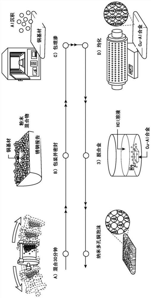
[0033] Aluminum-copper alloy precursors were synthesized using the inclusion infiltration method prior to dealloying. figure 1 A simplified diagram of the overall processing route is shown. The first step shows the mixing of the powders used in the embedding infiltration process. The powder consists of 3% by weight NH as activator 4 Cl powder (100 microns, Alfa Aesar, USA), 15 wt% pure aluminum powder (99.8%, +325 mesh, Alfa Aesar, USA) as coating metal source and 82 wt% Al as filler 2 o 3 Powder (60 μm, Alfa Aesar, USA) composition. Mechanical mixing (8000-DMixer Mill, SPEX Sample Prep, USA) was performed for 30 minutes to obtain a homogeneously mixed powder. After mixing, package and seal using stainless steel wrappers ( figure 1 b) for subsequent heat treatment steps; then embedding infiltration at a constant 800°C ( figure 1 c) Duration of 15 minutes, 30 minutes, 3 hours, 6 hours, 12 hours or 15 hours to...

Embodiment 2

[0034] Embodiment 2: chemical tin coating process

[0035] To demonstrate the performance of the as-synthesized nanoporous copper as an anode for lithium-ion batteries, a high-capacity anode active material (tin) was coated onto nanoporous copper by electroless plating. Immerse the nanoporous copper in the tin plating solution at 60 °C for 1 min. The tin plating solution consists of 2 grams of anhydrous tin(II) chloride (SnCl 2 2H 2 O), 2 grams of sodium phosphate monohydrate (sodiumphosphate monohydrate) (NaH 2 PO 2 2H 2 O), 10.5 grams of thiourea (CS(NH 2 ) 2 ) and 0.84 ml of concentrated hydrochloric acid in 200 ml of deionized water. Subsequently, the tin-coated nanoporous copper anode sample was heat-treated at 150 °C for 1 h in a tube furnace in an argon atmosphere.

Embodiment 3

[0036] Embodiment 3: Lithium-ion battery button cell cycle test

[0037] Copper disks were prepared with a diameter dimension of 11 mm and a thickness of 250 microns. A CR2032 type coin cell was assembled in a glove box in a dry argon atmosphere using a tin-coated nanoporous copper negative coupon as the working electrode and lithium metal foil for both the counter and reference electrodes. The electrolyte is a conventional 1.3 molar LiPF with ethylene carbonate (EC) and diethylene carbonate (DEC) in a volume ratio of 3:7 6 solution. Assembled coin cells containing tin-coated nanoporous copper negative electrode coupons were tested at a current density of 1 milliamp per square centimeter at a voltage range of 3.0 volts to 0.01 volts (for Li-ion / Li) at 25 degrees Celsius. Constant current test.

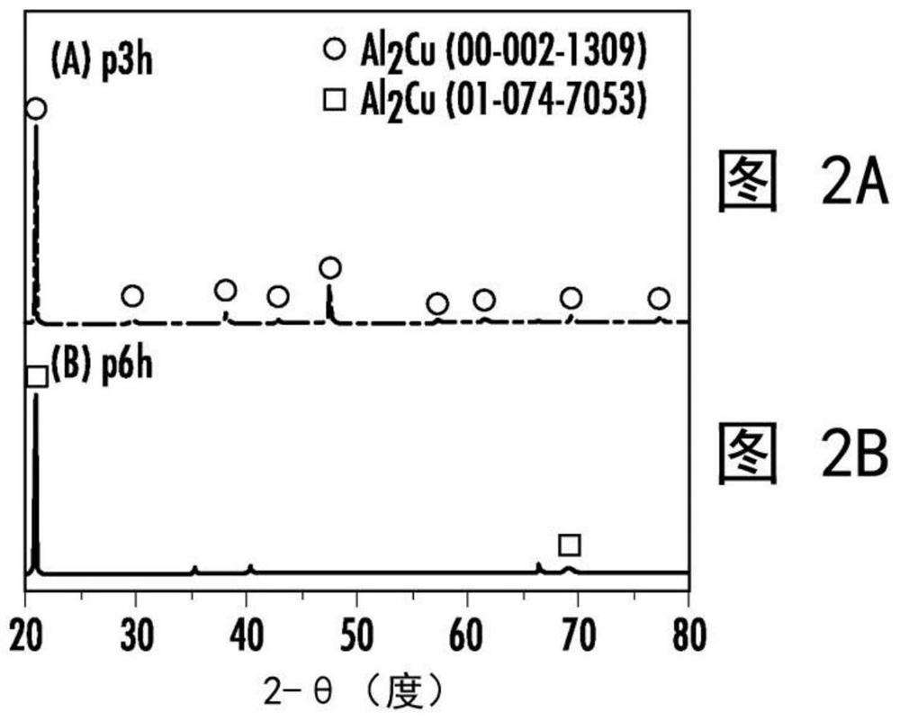
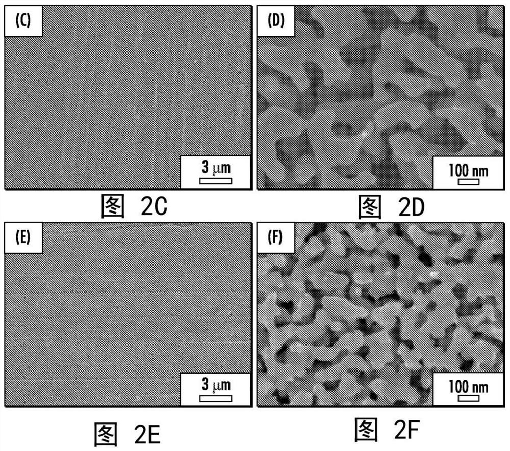
[0038] Example Results: Treatment of Al-Cu Precursors Based on Infiltration

[0039] The infiltration time was varied from 15 minutes to 15 hours to produce different aluminum-copp...


PUM

PropertyMeasurementUnit
diameteraaaaaaaaaa
diameteraaaaaaaaaa
thicknessaaaaaaaaaa

Abstract

A facile method is based on a pack-cementation process using large-area copper foil instead of copper powder. By controlling a pack-cementation time and an amount of alloying element (e.g., aluminum), a hierarchical microporous or nanoporous copper can be created. When coated with tin active material, the hierarchical microporous or nanoporous copper can be used as an advanced lithium-ion battery anode. A coin-cell test exhibited a four-fold higher areal capacity (e.g., 7.4 milliamp-hours per square centimeter without any performance degradation up to 20 cycles) as compared to a traditional graphite anode.

Description

[0001] Cross References to Related Applications [0002] This patent application claims the benefit of U.S. Patent Application 62 / 781,579, filed December 18, 2018, which is incorporated by reference together with all other references cited in this application. technical field [0003] The present invention relates to the field of metal electrodes, and more particularly to techniques for fabricating large-area copper nanofoams with layered structures for use as advanced electrodes in energy devices including batteries and energy storage units. Background technique [0004] Fabrication techniques to achieve dealloyed nanoporous copper have not been applied in practice. This is because any result has small dimensions and poor mechanical properties caused by using metal "powders" to create precursor alloys prior to dealloying. [0005] Therefore, there is a need for improved electrode materials with carefully designed structures for Li-ion batteries to increase Li-ion battery ...

Claims


Application Information

Patent Timeline
Patent Type & Authority Applications(China)
IPC IPC(8): C22C3/00B22F3/11H01M4/66H01M4/80
CPCC22C3/00C22C1/08B22F3/1103B22F2998/10Y02E60/10C23C10/36C23C10/38C23C10/44C23C10/48H01M4/133H01M4/134H01M4/387H01M4/362H01M4/382H01M4/483H01M4/808H01M4/661C22C9/01C22C21/12C23C10/00C22C1/0425B22F2301/052B22F2301/10H01M10/0525
Inventor 韩基甲朴惠智洪基哲崔喜满
Owner 赛莫必乐公司
Why Eureka
Try Eureka