An On-Line Voltage Drop Monitoring Circuit for Junction Temperature Monitoring

A technology for conducting voltage drop and monitoring circuits. It is applied in the direction of measuring electricity, measuring electrical variables, and measuring devices. It can solve problems such as high cost and main circuit interference, and achieve the effects of optimizing measurement errors, reducing costs, and suppressing effects.

Active Publication Date: 2022-07-19
SOUTHWEST JIAOTONG UNIV
View PDF3 Cites 0 Cited by
  • Summary
  • Abstract
  • Description
  • Claims
  • Application Information

AI Technical Summary

Problems solved by technology

[0005] At present, the voltage clamping circuit design, short-circuit risk and measurement accuracy of the on-line voltage drop monitoring circuit are the limitations of V ce Important reasons for the application of measurement circuits to actual working conditions
[0006] The voltage clamping circuit in the invention patent with application number 201611049398.3 provides an on-line monitoring circuit for conduction voltage drop, but its clamping circuit is composed of diodes in series with floating voltage-resistant isolation power supply, and its cost is relatively high. When the clamping circuit relies on Isolated power supply with high immunity to common mode transients, otherwise it will cause interference to the main circuit

Method used


Image

  • An On-Line Voltage Drop Monitoring Circuit for Junction Temperature Monitoring
  • An On-Line Voltage Drop Monitoring Circuit for Junction Temperature Monitoring
  • An On-Line Voltage Drop Monitoring Circuit for Junction Temperature Monitoring

Examples


Embodiment 1

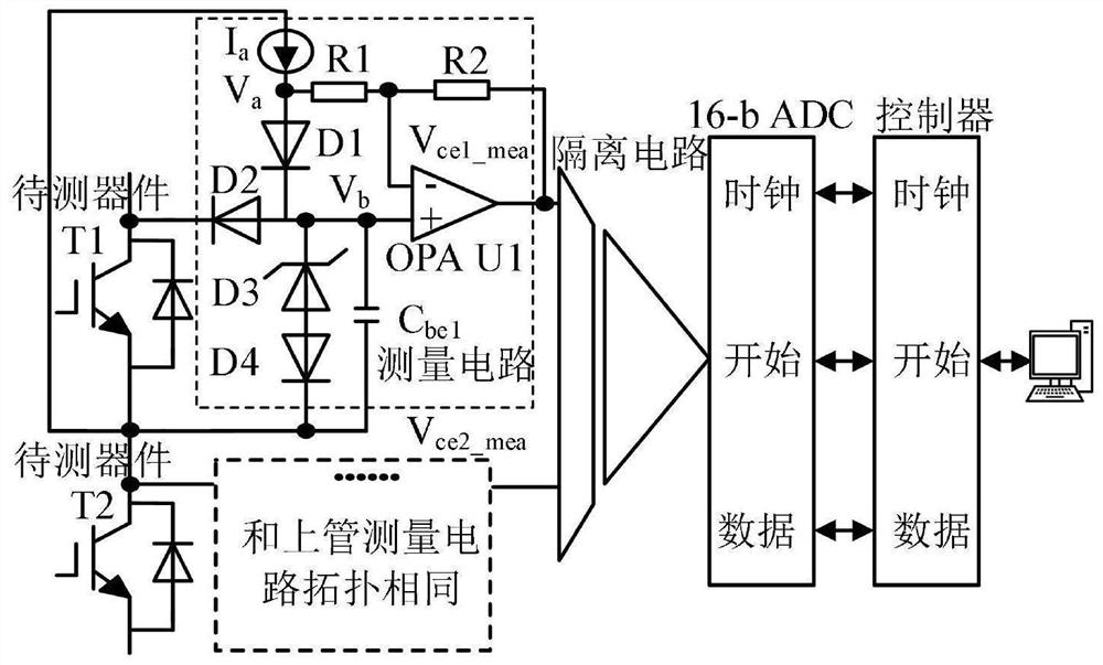
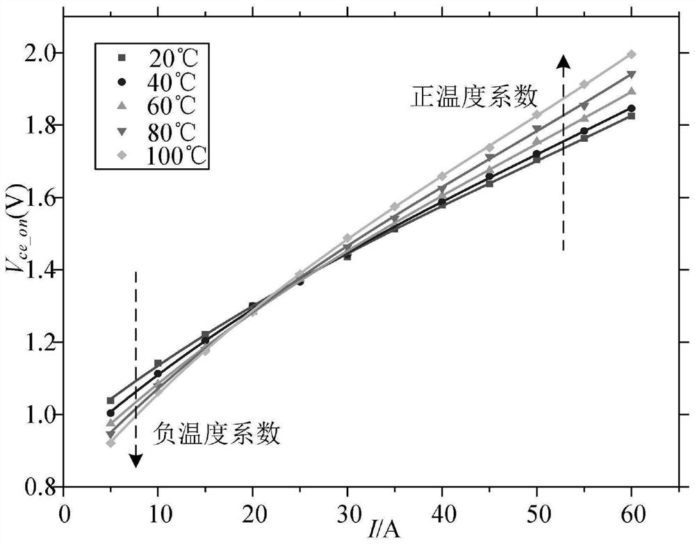
[0035] Carry out double-pulse test verification and offline correction operation for the IGBT module used in the traction rectifier. First, the on-line voltage drop monitoring circuit is connected in parallel on both sides of the collector and emitter of the upper and lower bridge arm IGBT modules, and then the IGBT modules are fixed in On constant temperature boards with different temperatures, after the junction temperature is stable, perform a double-pulse test. When the current passing through the upper bridge arm IGBT increases, record the conduction voltage drop of the upper tube through different currents at the junction temperature at this moment. The on-voltage drop and collector current data at the junction temperature are fitted, and the relationship between the junction temperature, on-voltage drop and current of the top-tube IGBT is shown in image 3 shown. When the upper tube IGBT is turned off, the clamping circuit in its conduction voltage drop measurement circui...

Embodiment 2

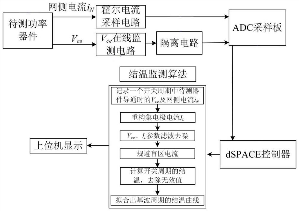
[0040] Example 2: To monitor the junction temperature of the IGBT chip in the traction rectifier, the on-line voltage drop monitoring circuit of the present invention is connected in parallel to the collector and emitter ends of the upper and lower bridge arm IGBT modules respectively. Then connect the on-line monitoring circuit of the upper and lower bridge arms to the isolation circuit, then connect the isolation circuit to the 16-bit ADC converter, and then transmit it to the DSP controller. When the output value of the measurement circuit is greater than 0V and less than the clamping voltage When the output value is less than 0V, it is the on-voltage drop value of the reverse diode chip. The grid-side current of the traction rectifier is collected by the current sampling circuit, passed through the 16-bit ADC converter, and then transmitted to the DSP controller. After processing the current signal, the current waveform passing through the IGBT chip is obtained. The juncti...

Embodiment 3

[0042] Example 3: The junction temperature monitoring was performed on the IGBT chip in the accelerated aging test platform, and the on-line voltage drop monitoring circuit of the present invention was connected in parallel to both ends of the collector and the emitter of the IGBT module to be tested. Then set V ce The output of the online monitoring circuit is passed to the controller, and the junction temperature is calculated through the offline corrected junction temperature relationship. Figure 7 The junction temperature monitoring results of this paper's measurement circuit and infrared thermometer in the accelerated aging test bench are shown.


PUM


Abstract

The invention discloses an on-line voltage drop monitoring circuit for junction temperature monitoring. The processor; the conduction voltage drop measurement circuits of the upper and lower bridge arms are consistent, in which the voltage clamping circuit is composed of ultra-fast recovery diodes connected in series in the direction of the Zener tube, and nF level capacitors are connected in parallel to suppress negative voltage overshoot; the conduction voltage of the upper and lower bridge arms is The output of the drop measurement circuit is connected to the isolation circuit, and then connected to the 16-bit ADC converter, and finally sent to the digital signal processor for processing. The junction temperature of the upper and lower bridge arm IGBT and diode chips can be monitored through the functional relationship of offline fitting. The monitoring circuit of the invention is simple and reliable, has high measurement accuracy, can isolate high voltage, and can be used normally in the converter and the accelerated aging test platform.

Description

technical field [0001] The invention belongs to the technical field of power electronics, and in particular relates to an on-line monitoring circuit for conducting voltage drop for monitoring junction temperature. Background technique [0002] As an important power semiconductor device for energy conversion and transmission, since its inception, IGBT has attracted a lot of attention in the fields of rail transit, smart grid, aerospace and other fields due to its high withstand voltage, reduced on-state voltage, and fast switching speed. In the converter, the reliable operation of IGBT is an important guarantee for realizing high-performance energy conversion, and plays an important role in the reliable operation of the entire power electronic system. Temperature cycling and steady-state temperature significantly affect the aging and failure of power devices. Therefore, monitoring the junction temperature of the IGBT plays an important role in ensuring the reliable operation...

Claims


Application Information

Patent Timeline
Patent Type & Authority Patents(China)
IPC IPC(8): G01R31/26
CPCG01R31/2619
Inventor 葛兴来杨旭冯晓云王惠民许智亮杨顺风宋文胜
Owner SOUTHWEST JIAOTONG UNIV
Why Eureka
Try Eureka