
Dry ice cleaning method and dry ice cleaning machine for furnace tube

A technology of dry ice cleaning and furnace tubes, which is applied in the direction of cleaning heat transfer devices, grain processing, lighting and heating equipment, etc., and can solve the problems of economizers affecting heat recovery efficiency, equipment corrosion, and affecting unit operation safety, etc.

Pending Publication Date: 2021-10-08
上海艺佳众翼工程建设有限公司
View PDF0 Cites 0 Cited by
  • Summary
  • Abstract
  • Description
  • Claims
  • Application Information

AI Technical Summary

Problems solved by technology

[0006] Aiming at the deficiencies of the prior art, the present invention provides a dry ice cleaning method and a dry ice cleaning machine for furnace tubes, which solves the problem that after a waste heat boiler has been used for a long time, the fouling of the economizer seriously affects the heat recovery efficiency and even affects the operation safety of the unit , to solve the problem of slow washing speed with high-pressure water, incomplete cleaning, and water easily entering the rotary air preheater during washing, which may affect the safety of the electrical equipment of the unit
Solved the method of cleaning the economizer with chemical reagents, but it is easy to cause corrosion to the equipment, and the problem that the reagents and waste materials will also affect the environment if they are not properly disposed of

Method used


Image

  • Dry ice cleaning method and dry ice cleaning machine for furnace tube
  • Dry ice cleaning method and dry ice cleaning machine for furnace tube
  • Dry ice cleaning method and dry ice cleaning machine for furnace tube

Examples


Embodiment 1

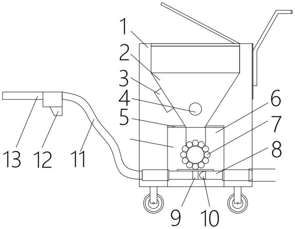
[0026] see figure 1 , the present invention provides the following technical solutions:

[0027] The dry ice cleaning machine for furnace tubes is characterized in that it includes a main box body 1, a conical hopper 2 is arranged inside the main box body 1, a vibrator 3 is installed on the side of the hopper 2, and a stirring roller is arranged inside the hopper 2 4. The outlet of the hopper 2 is provided with a flow sensor 5, and the outlet of the hopper 2 leads to the airlock feeder 7 in the feeding box 6. The outlet of the feeding box 6 is inserted in the radial direction of a high-speed air pipe 8, and the high-speed air pipe 8 is also A T-shaped groove 9 and a high-speed air nozzle 10 are provided. The outlet of the high-speed air pipeline 8 is connected to one end of a hose 11 , and the other end of the hose 11 is equipped with a spray gun 12 .

Embodiment 2

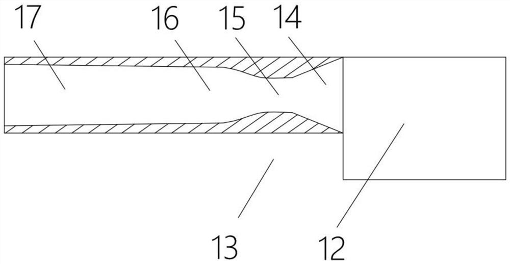
[0029] see figure 2 , the present invention provides the following technical solutions:

[0030] As described in Example 1, the dry ice blasting machine for furnace tubes is characterized in that: the convergent diverter nozzle 13 is sequentially provided with a nozzle joint 14, a nozzle neck 15, a nozzle first diffuser 16 and a nozzle from the tail to the head. The second diffuser 17 .

Embodiment 3

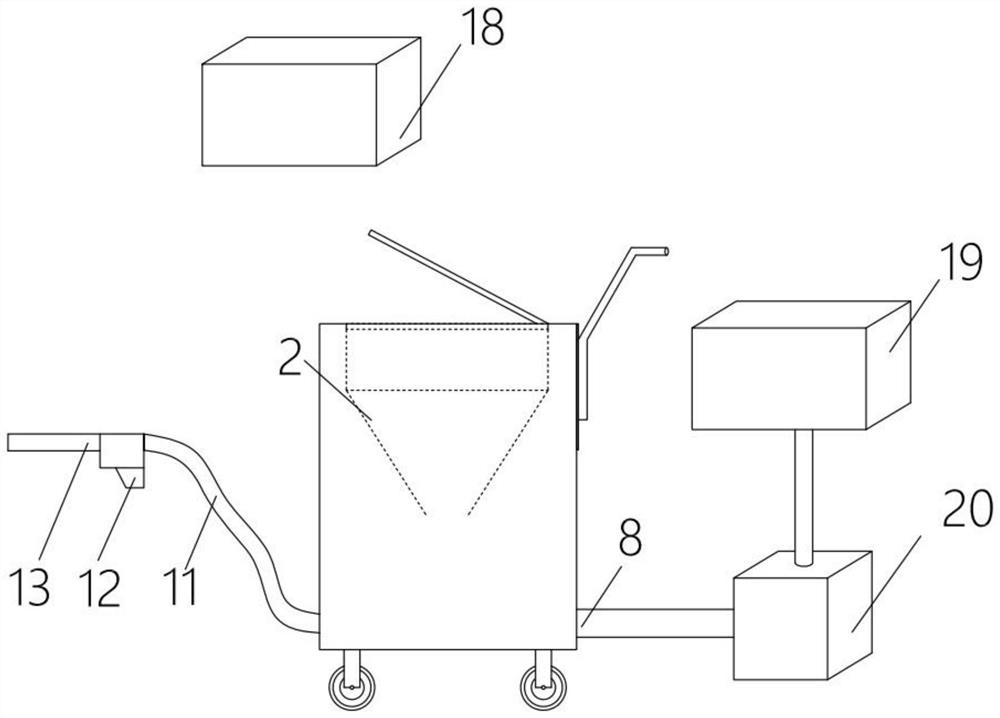
[0032] see image 3 , the present invention provides the following technical solutions:

[0033] The dry ice cleaning method for furnace tubes is characterized in that: the dry ice cleaning machine for the waste heat boiler economizer described in Embodiment 1 or 2 is used in the dry ice cleaning of the economizer of the waste heat boiler.

[0034] Preferably, the dry ice cleaning method for furnace tubes includes the following steps: putting the dry ice in the dry ice incubator 18 into the hopper 2, and transporting the compressed air to the high-speed air pipeline 8 after being processed by the air compressor 19 and the dryer 20 in sequence, Aim the converging and splitting nozzle 13 at the fouling place of the economizer, and run the dry ice blasting machine to start cleaning.

[0035] It solves the problem that after long-term use of the waste heat boiler, the fouling of the economizer seriously affects the heat recovery efficiency and even affects the safety of the unit ...


PUM


Abstract

The invention belongs to the field of petrochemical equipment cleaning, and particularly relates to a dry ice cleaning method and a dry ice cleaning machine for a furnace tube. The dry ice cleaning machine for the furnace tube comprises a main box body, wherein a hopper, a vibrator, a stirring roller, a flow sensor, a feeding box, an airlock feeder, a high-speed air pipeline, a T-shaped groove, a high-speed air nozzle, a hose and a spray gun are arranged in the main box body; and a convergent flow distribution nozzle is installed on a spray gun head and provided with a nozzle connector, a nozzle neck, a first nozzle diffusion part and a second nozzle diffusion part. The corresponding dry ice cleaning method comprises the steps that dry ice is put into the hopper, compressed air is sequentially treated through the air compressor and a drying machine and then conveyed to the high-speed air pipeline, the convergence flow distribution nozzle is aligned to the scaling position of an economizer, and the dry ice cleaning machine is operated to start cleaning. The problem that after a waste heat boiler is used for a long time, scale deposition of the economizer seriously affects the heat recovery efficiency and even affects unit operation safety is solved, and the problem that a traditional cleaning method is poor in effect is solved.

Description

technical field [0001] The invention belongs to the field of petrochemical equipment cleaning, and in particular relates to a dry ice cleaning method and a dry ice cleaning machine for furnace tubes. Background technique [0002] Petrochemical equipment often uses various furnace tubes such as waste heat boilers, economizers, and convection chambers. The waste heat boiler is a boiler that recovers waste gas, waste material or waste heat generated in chemical production and the heat generated by the combustion of combustible substances, and uses the recovered heat to produce hot water or steam for use in other sections. Fuel, gas, and coal are burned to produce high-temperature flue gas to release heat. The high-temperature flue gas first enters the furnace, then enters the waste heat recovery device of the front smoke box, then enters the pyrotechnic tube, and finally enters the waste heat recovery device in the flue of the rear smoke box. The flue gas becomes low-temperatu...

Claims


Application Information

Patent Timeline
Patent Type & Authority Applications(China)
IPC IPC(8): F28G13/00F28G15/04B02C4/00B02C19/16
CPCF28G13/00F28G15/04B02C4/00B02C19/16
Inventor 沈永峰
Owner 上海艺佳众翼工程建设有限公司
Learn More