
Micro-fluidic chip and preparation and application thereof

A microfluidic chip and channel layer technology, applied in the field of microfluidics, can solve the problems of lack of effective separation methods, inability to meet high sensitivity, and difficulty in popularization and application, so as to facilitate industrial promotion and application, improve mixing efficiency, and the method is simple and easy line effect

Inactive Publication Date: 2021-10-22
THE EYE HOSPITAL OF WENZHOU MEDICAL UNIV
View PDF9 Cites 0 Cited by
  • Summary
  • Abstract
  • Description
  • Claims
  • Application Information

AI Technical Summary

Problems solved by technology

However, due to its density and size highly overlapping with lipoproteins, and the lack of effective separation methods, plasma exosomes obtained using traditional exosome extraction and detection techniques are often mixed with a large amount of lipoproteins, which is far from meeting the requirements of high-sensitivity extraction. and requirements for testing biological samples required for liquid biopsy
The existing three-dimensional nanostructure microfluidic chip designed by the team of Professor Liu Bifeng of Huazhong University of Science and Technology, in which the array of micropillars is functionalized with intersecting multi-walled carbon nanotubes by chemical deposition, through specific recognition molecules (CD63) and unique topological nano Materials can efficiently capture exosomes, but this method is expensive and still in the stage of laboratory research, making it difficult to promote and apply it in the short term

Method used


Image

  • Micro-fluidic chip and preparation and application thereof
  • Micro-fluidic chip and preparation and application thereof
  • Micro-fluidic chip and preparation and application thereof

Examples


Embodiment 1

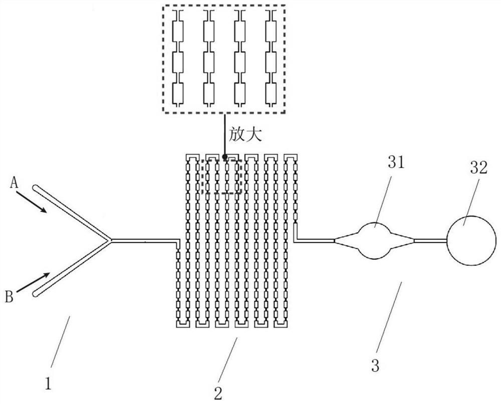
[0038] This embodiment provides a microfluidic chip, including a channel layer and a base layer, wherein the channel layer is bonded to the base layer by means of surface plasma treatment.

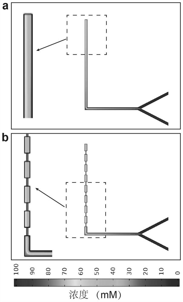
[0039] Among them, the further structural features of the channel layer are as attached figure 1 As shown, the above-mentioned channel layer includes a sampling area 1 , a mixing area 2 and a detection area 3 connected in sequence. In this embodiment, the sampling region 1 includes two sampling ports, and the sampling channel is in the shape of a "Y", and the width and height of the "Y"-shaped channel are both on the order of microns. Specifically, in this embodiment, The width of the "Y"-shaped channel is designed to be 200 μm, and the height is designed to be 100 μm. Sample A and sample B are respectively input from two injection ports, and then enter the mixing area 2 through the above-mentioned injection channel.

[0040] In other embodiments, the sampling channel can also be designe...

Embodiment 2

[0051] This implementation provides a microfluidic chip, which includes a channel layer and a base layer, wherein the channel layer is bonded to the above base layer by means of surface plasma treatment, and the specific preparation method is the same as that in Example 1.

[0052] Further, the structure of the channel layer in this embodiment is the same as that in Embodiment 1. Further, the channel layer in this embodiment can be made of PDMS, but in addition, PMMA or vinyl polymer can also be used instead.

[0053] The base layer can be made of a glass plate or a polyethylene plate. In this embodiment, a glass plate is selected as the material for making the base layer, and the surface of the glass plate is decorated with distearoylphosphatidylethanolamine-polyethylene glycol (DSPE-PEG). ).

[0054] Further, the microfluidic chip of this embodiment also includes a magnet, as attached Figure 5 As shown, the magnet is disposed below the first chamber.


PUM


Abstract

The invention provides a micro-fluidic chip which comprises a channel layer and a substrate layer; the channel layer comprises a sample introduction area, a mixing area and a detection area which are sequentially communicated; the mixing area comprises a plurality of mixing units; each mixing unit comprises at least one wide channel and at least one narrow channel, wherein the width of the wide channel is 100-300 microns, and the width of the narrow channel is 1 / 5-1 / 2 of the width of the wide channel; and target samples can be efficiently mixed, and functional areas including mixing, separation and detection are integrated on the chip at the same time, so that the requirements of reaction, separation, detection and the like can be met, and the production or research efficiency can be effectively improved. The obtained micro-fluidic chip can also be applied to the field of plasma lipoprotein and exosome separation, and is beneficial to promoting the application of lipoprotein and exosome in disease mechanism research and diagnosis.

Description

technical field [0001] The invention relates to the field of microfluidic technology, in particular to a microfluidic chip. Background technique [0002] With the development of semiconductor processing technology and microfluidic technology, chemical and biological chips based on microfluidic technology continue to emerge. Microfluidic technology is based on micro-processing technology. Functional units such as micro-pipelines and micro-reactors are processed on matrix materials such as glass and high molecular polymers, so as to realize the pre-treatment and sample addition involved in the fields of biology and chemistry. , reaction, separation, analysis, cell culture and other basic operating units are integrated or basically integrated on a chip of the size of a square, to replace a technical platform for various functions of conventional chemical or biological laboratories. Specifically, the microfluidic chip significantly improves the mixing efficiency of samples by r...

Claims


Application Information

Patent Timeline
IPC IPC(8): B01L3/00B01F13/00C12M1/34C12M1/00G01N33/92
CPCB01L3/502707B01L3/5027G01N33/92C12M47/04C12M23/16C12M41/46B01L2200/10B01L2300/12
Inventor 朱庆夫娄豆豆刘飞
Owner THE EYE HOSPITAL OF WENZHOU MEDICAL UNIV
Learn More