A converter primary dust removal system for reducing particulate matter emission and using method thereof

A dust removal system and particle technology, applied in the field of converter dust removal, can solve the problems of increasing investment, operation management and operation maintenance costs, reducing the space occupied by the dehydrator, and failing to meet environmental protection requirements, etc., to achieve good fluid mechanics performance, Optimize group layout and reduce system resistance

Active Publication Date: 2022-08-05
NORTHEASTERN UNIV LIAONING
View PDF12 Cites 0 Cited by
  • Summary
  • Abstract
  • Description
  • Claims
  • Application Information

AI Technical Summary

Problems solved by technology

[0011] (2) By adding or extending the length of the existing gas and water separation device for dust removal, the cooling effect is improved, and the gas is effectively separated from the water; the invention patent with application number 201510180601.X discloses a dust removal method that improves the effect of wet dust removal System and method; by connecting more than one dedusting dehydration tank in series behind the pipeline fan of the wet dedusting system, and designing the structure inside the tank, the flue gas is compressed, sprayed, decelerated, swirled, folded flow, filter, and then reduce the concentration of dusty gas emissions to 30mg / Nm 3 The following; the utility model patent with application number 201320135423.5 discloses a gas and water separation device for converter wet dedusting; by prolonging the residence time of turbid circulating water in the dedusting equipment, the gas is effectively separated from the water, reducing the amount of gas emission, improve gas recovery rate; utility model patent application number 201820292564.0, announced a new OG dust removal system for converter flue gas; it uses ultra-clean dehydration dust collector to replace wet spin dehydrator, and ultra-clean dehydration dust removal The middle part of the device is replaced by a tube bundle, and the outer wall of the tube bundle is cooled by the external ambient air, which improves the cooling effect; however, the addition of a new gas and water separation device will increase the cost of investment, operation management and operation and maintenance, and prolong the existing dust removal. , The length of the water separation device needs to increase the space; at the same time, the dust concentration of the gas after dust removal is still only reduced to 30mg / Nm 3 , also unable to meet the current ≤20mg / Nm 3 environmental protection requirements;
[0012] (3) By adjusting the throat opening degree of the secondary flap venturi tube and the annular seam opening degree of the annular venturi tube, the airflow surge phenomenon of the new OG method is overcome; the utility model patent with the application number 201621409178.2 has published a A converter dust removal system, through the online monitoring device to detect the dust content in the flue gas, the control unit adjusts the speed of the fan according to the online dust content data, and automatically adjusts the throat opening degree of the secondary flap venturi tube, the ring seam venturi tube The opening of the ring seam ensures that the flue gas treated by the converter dust removal device meets the requirements of environmental protection; the invention patent application number is 201410285436. The water pipe and the curved swirl spray gun dehydrator reduce the space occupied by the dehydrator and meet the dehydration effect of the first dust removal; by adjusting the size of the throat ring seam of the secondary venturi tube, the problem that the fan speed cannot be operated at a low speed is solved, and the problem is overcome. The airflow surge phenomenon has been eliminated; the invention patent with the application number 201611254527.2 has announced a double closed-loop dynamic optimization OG method for converter gas recovery and fan energy-saving control method. The air pressure controls the speed of the fan, and through the organic combination of the two, the gas recovery and the energy-saving effect of the fan are guaranteed; however, in the above-mentioned published patents, adjusting the opening of the Venturi tube will increase the flow rate of dust and gas in the device, resulting in dust erosion on the inner wall of the device exacerbated and shortened system life

Method used


Image

  • A converter primary dust removal system for reducing particulate matter emission and using method thereof
  • A converter primary dust removal system for reducing particulate matter emission and using method thereof
  • A converter primary dust removal system for reducing particulate matter emission and using method thereof

Examples


Embodiment 1

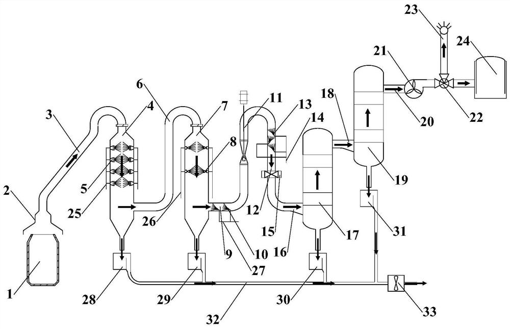
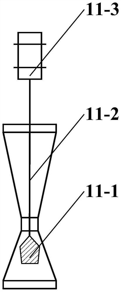
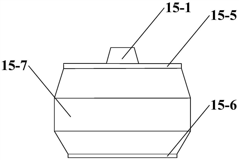
[0081] The structure of the primary dust removal system of the converter to reduce the emission of particulate matter is as follows: figure 1 As shown, it includes converter 1, primary spray washing tower 4, secondary spray washing tower 7, annular slit venturi 11, flue gas water mist separator 15, first cyclone dehydrator 17 and second cyclone dehydrator 19;

[0082] The flue gas collection hood 2 is matched with the converter 1, and the flue gas collection hood 2 is communicated with the top of the primary spray washing tower 4 through the vaporization cooling flue 3, and the lower part of the primary spray washing tower 4 and the top of the secondary spray washing tower 7 are adjusted by the system. The pressure pipe 6 is communicated, and the lower part of the secondary spray washing tower 7 is communicated with the lower end of the annular slot venturi 11 through the first flue gas pipeline 9; , the annular slit venturi 11 and the dust removal pipe 12 are communicated th...

Embodiment 2

[0113] The structure of the converter primary dust removal system for reducing particulate matter emission is the same as that in Example 1, except that:

[0114] (1) The first-stage conical blade swirl plate is composed of 4 blades, the second-stage conical blade swirl plate is composed of 4 blades, and the third-stage conical blade swirl plate is composed of 6 blades;

[0115] (2) The blade bending inclination angle of the first-stage conical blade swirl plate is 7°; the blade bending inclination angle of the second-stage conical blade swirl plate is 7°; the blade bending inclination angle of the third-stage conical blade swirl plate is 9° ;

[0116] (3) There are 5 groups of dual-fluid aerosol spray guns inside the primary spray washing tower, and each group of dual-fluid aerosol spray guns has 4 nozzles; There are 5 nozzles in the pair of spray type spiral spray gun;

[0117] (4) There are 3 air-water atomizing spray guns in the first flue gas pipeline;

[0118] (5) The...

Embodiment 3

[0130] The structure of the converter primary dust removal system for reducing particulate matter emission is the same as that in Example 1, except that:

[0131] (1) The first-stage conical blade swirl plate is composed of 5 blades, the second-stage conical blade swirl plate is composed of 5 blades, and the third-stage conical blade swirl plate is composed of 7 blades;

[0132] (2) The blade bending inclination angle of the first-stage conical blade swirl plate is 9°; the blade bending inclination angle of the second-stage conical blade swirl plate is 9°; the blade bending inclination angle of the third-stage conical blade swirl plate is 10° ;

[0133] (3) There are 6 groups of dual-fluid aerosol spray guns inside the primary spray washing tower, and each group of dual-fluid aerosol spray guns has 6 nozzles; the interior of the secondary spray washing tower is equipped with 4 sets of pair-spraying spiral spray guns, each with 6 nozzles. There are 3 nozzles for the pair of sp...


PUM


Abstract

A primary dust removal system for a converter for reducing particulate matter emission and a method for using the same. The gas-water mist separator, the first cyclone dehydrator, the second cyclone dehydrator and the primary dust removal fan are connected in series in sequence; the method is as follows: during the converter steelmaking process, the primary dust removal fan is started, and the converter flue gas is sprayed in the primary spray washing tower, The secondary spray scrubber and the first flue gas pipeline are washed in sequence, accelerated by the annular slit venturi, and then sprayed with high-pressure steam to form water mist. The water flow is separated from the flue gas, and the flue gas is dehydrated by the first cyclone dehydrator and the second cyclone dehydrator, and then enters the primary dust removal fan. The method of the invention can ensure that the content of the particulate matter in the flue gas reaches 15mg / Nm 3 Below, the emission requirements are met.

Description

technical field [0001] The invention relates to the technical field of converter dust removal treatment, in particular to a converter primary dust removal system for reducing particulate matter emission and a method for using the same. Background technique [0002] In the process of oxygen blowing smelting in the converter, the molten iron and oxygen in the furnace chemically react to generate high temperature flue gas up to 1600℃, which is called converter gas, and its main components are CO, CO 2 , SO 2 , N 2 , O 2 It has the characteristics of high temperature, toxic, flammable and explosive, and high dust content; in the middle stage of smelting, the CO content is as high as 80% or more, and the iron-containing dust concentration reaches 150-200mg / Nm 3 , its calorific value is high, the quantity is large, and it is a valuable secondary energy. Effective recycling of converter gas can not only greatly reduce the production cost of the steelmaking process and realize n...

Claims


Application Information

Patent Timeline
Patent Type & Authority Patents(China)
IPC IPC(8): C21C5/40
CPCC21C5/40Y02P10/20
Inventor 朱苗勇刘志远蔡兆镇娄文涛姜嵇银
Owner NORTHEASTERN UNIV LIAONING
Why Eureka
Try Eureka