Probe type fluorescent confocal endoscope coupling objective lens optical system

A technology of optical system and coupling object, applied in the field of endoscope system, can solve the problems of short working distance, smaller design space of optical fiber connector, performance loss, etc., and achieve the effect of eliminating spherical aberration

Active Publication Date: 2021-11-12
EZHOU INST OF IND TECH HUAZHONG UNIV OF SCI & TECH +1
View PDF15 Cites 2 Cited by
  • Summary
  • Abstract
  • Description
  • Claims
  • Application Information

AI Technical Summary

Problems solved by technology

[0003] The working distance of the traditional coupling objective lens is relatively short, resulting in smaller design space for subsequent fiber optic connectors, more difficult structural design, and higher costs
In addition, the traditional coupling objective lens is designed for the white light band, and lacks a coupling objective lens specially designed for 488nm laser and fluorescence bands, resulting in loss of performance

Method used


Image

  • Probe type fluorescent confocal endoscope coupling objective lens optical system
  • Probe type fluorescent confocal endoscope coupling objective lens optical system
  • Probe type fluorescent confocal endoscope coupling objective lens optical system

Examples


Embodiment 1

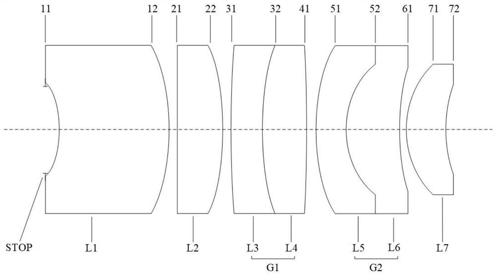
[0079] In embodiment 1, the structural representation of coupling objective optical system is as follows figure 1 As shown, the specific data are shown in Table 1: Among them, the focal length f=7.56mm; NA=0.35;

[0080] Table 1

[0081]

[0082]

[0083] Table 1 shows the basic data of the coupled objective optical system of Example 1, wherein STOP represents the aperture stop, and IMAGE represents the imaging plane.

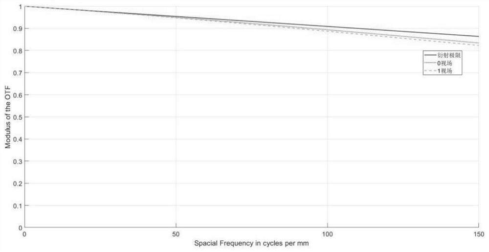
[0084] figure 2 It is the MTF modulation transfer function curve emulation figure of coupling objective lens optical system in embodiment 1, and abscissa is spatial frequency (unit lp / mm), and ordinate is MTF, and maximum is 1, and minimum is 0; Among the figure, abscissa is spatial frequency , the maximum is 150lp / mm, and the minimum is 0. Depend on figure 2 It can be seen that the MTF is close to the diffraction limit, and the design aberration of the objective lens coupled with the objective lens optical system provided by the present application...

Embodiment 2

[0089] In embodiment 2, the structural representation of coupling objective optical system is as figure 1 As shown, the specific data are shown in Table 2: Among them, the focal length f=7.56mm; NA=0.35;

[0090] Table 2

[0091] face number Radius of curvature / mm Center thickness / mm Material stop ∞ 0.564 11 -7.246 6.588 H-LAK52 12 -17.527 0.500 21 ∞ 2.866 H-FK61B 22 -17.547 0.500 31 69.038 2.000 H-ZF3 32 18.304 3.000 H-LAK52 41 -46.930 0.450 51 11.925 2.000 H-ZF6 52 6.000 3.420 H-LAK52 61 22.721 0.450 71 6.500 2.682 H-FK61B 72 10.523 5.278 IMAGE ∞

[0092]Table 2 shows the basic data of the coupled objective optical system of Example 2. Among them, STOP represents the aperture stop, and IMAGE represents the imaging plane.

[0093] Image 6 Be the MTF modulation transfer function curve emulation figure of coupling objective lens optical syst...

Embodiment 3

[0098] In embodiment 3, the structural representation of coupling objective optical system is as follows figure 1 As shown, the specific data are shown in Table 3: focal length f=7.56mm; NA=0.35;

[0099] table 3

[0100] face number Radius of curvature / mm Center thickness / mm Material stop ∞ 0.724 11 -6.044 7.777 H-LAK52 12 -12.202 0.500 21 ∞ 2.896 H-FK61B 22 -16.919 0.500 31 65.803 2.000 H-ZF3 32 19.464 2.919 H-LAK52 41 -72.565 0.500 51 13.365 2.000 H-ZF6 52 5.884 3.364 H-LAK52 61 16.622 0.500 71 5.770 2.806 H-FK61B 72 8.784 5.344 IMAGE ∞

[0101] Table 3 shows the basic data of the coupled objective optical system of Example 3. Among them, STOP represents the aperture stop, and IMAGE represents the imaging plane.

[0102] Figure 10 Be the MTF modulation transfer function curve emulation figure of the coupled objective lens optical system ...


PUM


Abstract

The invention relates to a probe type fluorescent confocal endoscope coupling objective lens optical system. The probe type fluorescent confocal endoscope coupling objective lens optical system comprises a diaphragm, a first lens, a second lens, a first lens group, a second lens group and a seventh lens which are sequentially arranged from an object plane to an image plane along an optical axis, wherein each of the first lens group and the first lens group is a double-gluing lens; the first lens group comprises a third lens and a fourth lens which are sequentially arranged from the object plane to the image plane along the optical axis; and the second lens group comprises a fifth lens and a sixth lens which are sequentially arranged from the object plane to the image plane along the optical axis. The coupling objective lens optical system provided by the invention basically eliminates spherical aberration, coma, astigmatism, field curvature, distortion and axial chromatic aberration, and meets the requirements of a flat-field apochromatic objective lens; and the axial difference between the optimal focus point of the edge view field and the optimal focus point of the center view field is smaller than 2 lambda / NA2, the achromatic aberration of 515 nm light and 550 nm light is eliminated, and the axial chromatic aberration of 488 nm light and 515 nm light is smaller than 2 lambda / NA2, wherein lambda is the central wavelength, and NA is the numerical aperture of the coupling objective optical system.

Description

technical field [0001] The invention belongs to the technical field of endoscope systems, and in particular relates to a probe-type fluorescence confocal endoscope coupling objective lens optical system. Background technique [0002] At present, the probe-type fluorescent confocal endoscope system needs to use 488nm laser as the light source. The laser passes through the optical path of the confocal host and then enters the image transmission fiber through the coupling objective lens. The image transmission fiber can be extended into the human digestive tract so that the laser can reach the digestive tract. Fluorescence is excited by the mucous membrane, and after being received by the image transmission fiber again, the fluorescence reaches the detector of the optical path of the confocal host through the coupled objective lens, thereby realizing confocal imaging. One of the core devices is the coupling objective lens, which is used to couple the image transmission fiber an...

Claims


Application Information

Patent Timeline
Patent Type & Authority Applications(China)
IPC IPC(8): A61B1/00G02B13/00
CPCA61B1/00165A61B1/00188G02B13/00
Inventor 刘谦蒋志豪付玲马骁萧
Owner EZHOU INST OF IND TECH HUAZHONG UNIV OF SCI & TECH
Why Eureka
Try Eureka