Constant temperature control MEMS gyroscope
A technology of constant temperature control and gyroscope, which is used in gyroscope/steering sensing equipment, gyro effect for speed measurement, instruments and other directions, which can solve the complex structure of MEMS gyroscope, limit the application of constant temperature control method, and large heat loss of off-chip heating structure and other problems, to achieve the effect of improving temperature stability, high sensitivity, and reducing power consumption
- Summary
- Abstract
- Description
- Claims
- Application Information
AI Technical Summary
Problems solved by technology
Method used
Image
Examples
Embodiment 1
[0044] It should be noted that the diagrams provided in this embodiment are only schematically illustrating the basic ideas of the present invention, and only the components related to the present invention are shown in the drawings rather than the number, shape and size of components in accordance with actual implementation Drawing, the type, quantity and proportion of each component can be changed arbitrarily during its actual implementation, and the component layout type may also be more complex.
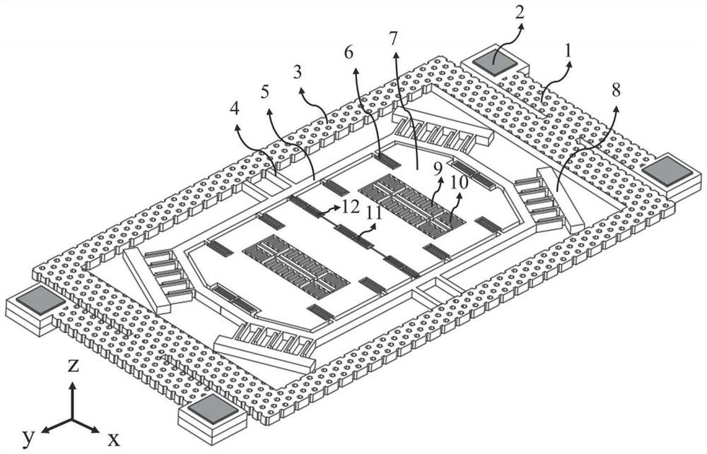
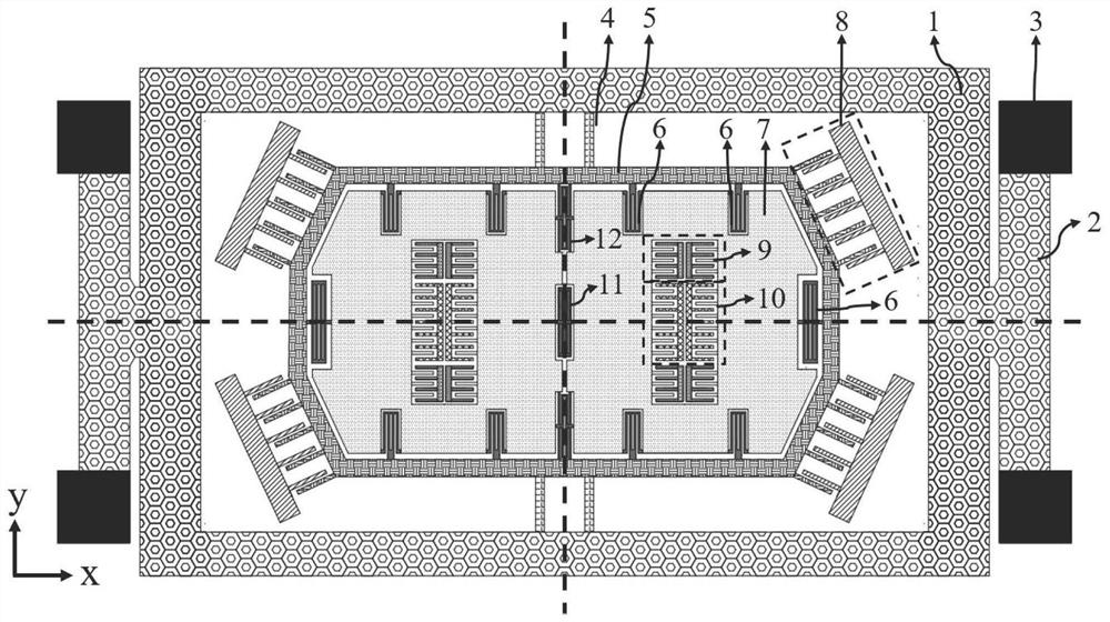
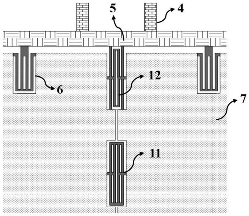
[0045] The three-dimensional and planar structure of the constant temperature control MEMS gyroscope of the present invention are as follows: figure 1 and figure 2 As shown, the MEMS gyroscope structure of the present invention consists of four fixed anchor points 3, four heating beams 2, a rectangular heat insulation frame 1, a detection frame 5, two mass blocks 7, two pairs of driving electrodes 10, and four sensing electrodes 8 , two pairs of drive detection electrodes 9, se...
Embodiment 2
[0061] Based on the constant temperature control MEMS gyroscope structure in Example 1, the actual temperature change of the overall structure of the gyroscope can be monitored in real time by means of resonant frequency temperature measurement. The temperature control principle diagram based on the frequency temperature measurement method is as follows Figure 11 shown. A bias voltage V can be applied between two fixed anchor points 3 located on the left side of the MEMS gyroscope structure bias and heating positive voltage V h , apply a bias voltage V between the two fixed anchor points 3 on the right bias and heating negative voltage -V h , the heating function can be realized. The driving frequency f can be output by driving the detection electrode 9, and the detection signal is fed back to the proportional-integral controller (PI), and the output heating voltage is controlled by PI, so that the resonance frequency f of the overall structure is controlled to a constant ...
Embodiment 3
[0063] Based on the planar structure of the MEMS gyroscope in Example 1, the positions of the heating beam 2 and the fixed anchor point 3 can be flexibly arranged, and the planar structure schematic diagram is as follows Figure 12 shown. One end of the four heating beams 2 is located at the four corners of the rectangular heat insulating frame 1, and the other end of each heating beam 2 is respectively connected to a fixed anchor point 3, and the fixed anchor points 3 are located on both sides of the rectangular heat insulating frame 1 in the Y direction. This structure further increases the rigidity of the heating structure of the constant temperature control gyroscope, and can further reduce the influence of the structure of the heating beam 2 and the rectangular heat insulation frame 1 on the driving mode and detection mode of the gyroscope, thereby reducing the heating beam 2 and the rectangular Negative impact of thermal insulation frame 1 on MEMS gyroscope performance. ...
PUM
 Abstract
Description
Claims
Application Information
 - R&D
- Intellectual Property
- Life Sciences
- Materials
- Tech Scout
- Unparalleled Data Quality
- Higher Quality Content
- 60% Fewer Hallucinations
Browse by: Latest US Patents, China's latest patents, Technical Efficacy Thesaurus, Application Domain, Technology Topic, Popular Technical Reports.
© 2025 PatSnap. All rights reserved.Legal|Privacy policy|Modern Slavery Act Transparency Statement|Sitemap|About US| Contact US: help@patsnap.com


