Anti-clogging clarifier injection device for glass manufacturing

A glass manufacturing and spraying device technology, applied in spraying devices, glass manufacturing equipment, manufacturing tools, etc., can solve the problems of glass spraying operation rate reduction, glass damage, blockage, etc., achieve uniform and comprehensive spraying operation, improve adaptability, prevent blocking effect

Active Publication Date: 2022-04-19
徐州市威固特种玻璃有限公司
View PDF0 Cites 0 Cited by
  • Summary
  • Abstract
  • Description
  • Claims
  • Application Information

AI Technical Summary

Problems solved by technology

[0005] The purpose of the present invention is to provide an anti-clogging clarifier spraying device for glass manufacturing, to solve the above-mentioned background technology that requires manual placement and position adjustment of the glass, which leads to a decrease in the spraying speed of the glass, and frequent spraying intervals. Too long clarifying agent will often solidify and block the nozzle of the spraying device, and the existing device can only spray on one place, and the user can only move the glass to adjust the spraying position, which is too cumbersome and may damage the glass

Method used


Image

  • Anti-clogging clarifier injection device for glass manufacturing
  • Anti-clogging clarifier injection device for glass manufacturing
  • Anti-clogging clarifier injection device for glass manufacturing

Examples


Embodiment 2

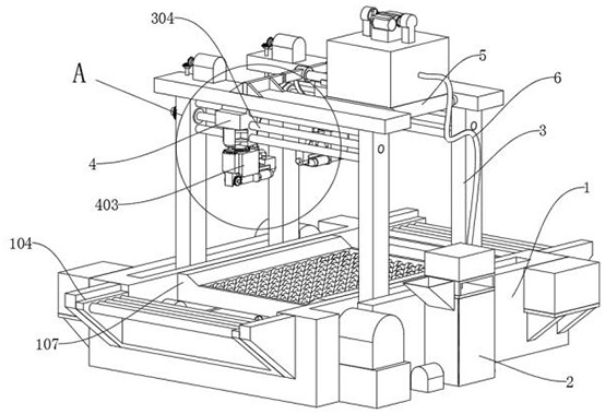
[0042] Example TWO, e.g., Figure 9 As shown, other structures remain unchanged, can be added bearing structure, bearing structure comprising: collection frame 108, collection frame 108 is set on the inside of the jet stage 1, evacuation board 1081, evacuation board 1081 is set on the inside of the collection frame 108, conveying tank 1082, conveyor tank 1082 is opened on the top of the evacuation carrier plate 1081, discharge carrier pipe 1083, discharge carrier pipe 1083 is set on the side of the injection stage 1, discharge pipe 1083 is connected with the conveyor tank 1082 When the device is sprayed, the collection frame 108 and the evacuation carrier plate 1081 are combined, which can undertake storage of the excess clarifier that is sprayed and flowed down, thereby preventing unnecessary pollution caused by the scattered flow of excess clarifier, which can ensure the cleanliness of the entire working space, and at the same time can recycle the excess clarifier to reduce unne...

Embodiment 3

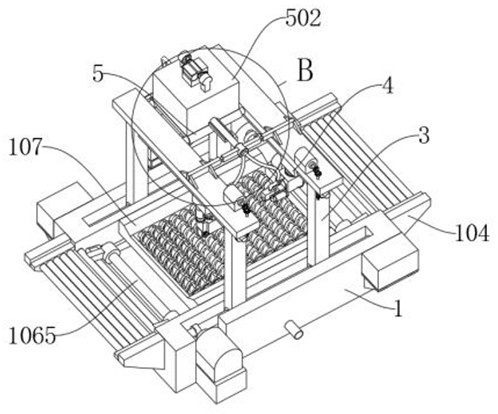
[0043] Example THREE, e.g., Figure 14As shown, other structures unchanged, can be added pressure structure, the pressure structure comprising: drive slide 506, drive slide 506 is provided at the top of the active storage carrier box 502, conveying pressure plate 5061, conveying pressure plate 5061 is set at the end of the drive slide 506, while active in the storage carrier box 502 inside, drive slotting 5062, drive slotting 5062 opened at the other end of the drive slide 506, mounting carrier 5063, mounting carrier 5063 installed on the top of the storage carrier box 502, Reciprocating motor 5064, reciprocating motor 5064 is installed on both sides of the mounting carrier 5063, reciprocating shaft 5065, reciprocating shaft 5065 rotation is set on the inside of mounting carrier 5063, reciprocating rotor 5066, reciprocating rotor 5066 is set at both ends of the reciprocating shaft 5065; continuous rotation is driven by the reciprocating motor 5064 to drive the reciprocating shaft...


PUM


Abstract

The invention discloses an anti-clogging clarifying agent spraying device for glass manufacturing, which relates to the technical field of production and manufacturing auxiliary devices, in order to solve the problem that the existing device can only spray one place, and the user can only move the glass to adjust the spraying position ;Includes a spray carrier and a one-way carrier tube; the inner side of the top of the spray carrier is provided with an assembly loading shaft, and the inner side of the configuration carrier box is provided with a drive mixing structure; a guide column is provided between the load columns; There are telescopic pillars on the side, a storage box on the top of the top base of the load, a load-bearing convex plate on the side of the top base of the load, a transport connection tube on the side of the storage load box, and a one-way load tube on the side of the storage load box. The evenly mixed clarifying agent is transported to the interior of the storage tank, and transported to the spray joint through the transport connection tube and the shunt load tube. The angle adjustment motor drives the bearing tooth column to rotate, and drives the drive spray structure to sweep and spray the glass, so that the device can Spray the glass evenly over the entire surface.

Description

Technical field [0001] The present invention relates to the technical field of manufacturing auxiliary devices, specifically a clogging-proof glass manufacturing with clarifier spray device. Background [0002] Glass clarifiers are auxiliary chemical raw materials commonly used in glass production. Where the glass melting process of high temperature decomposition (gasification) to produce gas or reduce the viscosity of glass liquid, promote the elimination of bubbles in the glass liquid raw material is called a clarifier, according to the mechanism of action of glass clarification can be divided into: oxide clarifier (commonly known as: oxygen clarification), sulfate type clarifier (commonly known as: sulfur clarification), halide clarifier (commonly known as: halogen clarification) and compound clarifier (commonly known as: composite clarification), oxide clarifier oxide clarifier mainly arsenic, antimony oxide, sodium nitrate, ammonium nitrate, cerium dioxide and so on. [000...

Claims


Application Information

Patent Timeline
Patent Type & Authority Patents(China)
IPC IPC(8): B05B13/02B05B15/50B05B13/04B05B15/68B05B12/12C03B5/225C03C17/00
CPCB05B13/0221B05B15/50B05B13/0421B05B15/68B05B12/124C03B5/225C03C17/001
Inventor 葛祖根陆晔宋庆
Owner 徐州市威固特种玻璃有限公司
Why Eureka
Try Eureka