Low-CO2 partial pressure environment cement sintering system and cement clinker preparation method

An environment and cement technology, which is applied in the low CO2 partial pressure environment cement firing system and cement clinker preparation field, can solve the problems of increasing the heat consumption of the system, the crusting of the cyclone and the material pipe, and increasing the temperature of the exhaust gas at the outlet of the preheater, etc. , to increase the decomposition rate and facilitate combustion

Pending Publication Date: 2021-11-19
CBMI CONSTR
View PDF9 Cites 2 Cited by
  • Summary
  • Abstract
  • Description
  • Claims
  • Application Information

AI Technical Summary

Problems solved by technology

However, no matter whether the above cement kiln system is fed with air or pure oxygen, the CO in the decomposition furnace 2 Concentrations will be high, resulting in CO 2 The partial pressure is high, and CaCO 3 Decompose to produce CO 2 is a reversible chemical reaction, when CO 2 When the partial pressure is high, the reaction in the decomposition furnace will decrease accordingly, and the CaCO 3 The decomposition rate will be affected, and want CaCO 3 As the decomposition rate of CaCO increases, it is necessary to increase the temperature in the decomposition furnace, and according to experiments, if you want to make CaCO 3

Method used


Image

  • Low-CO2 partial pressure environment cement sintering system and cement clinker preparation method
  • Low-CO2 partial pressure environment cement sintering system and cement clinker preparation method

Examples


Embodiment Construction

[0033] The following will clearly and completely describe the technical solutions in the embodiments of the present invention with reference to the accompanying drawings in the embodiments of the present invention. Obviously, the described embodiments are only some, not all, embodiments of the present invention. Based on the embodiments of the present invention, all other embodiments obtained by persons of ordinary skill in the art without making creative efforts belong to the protection scope of the present invention.

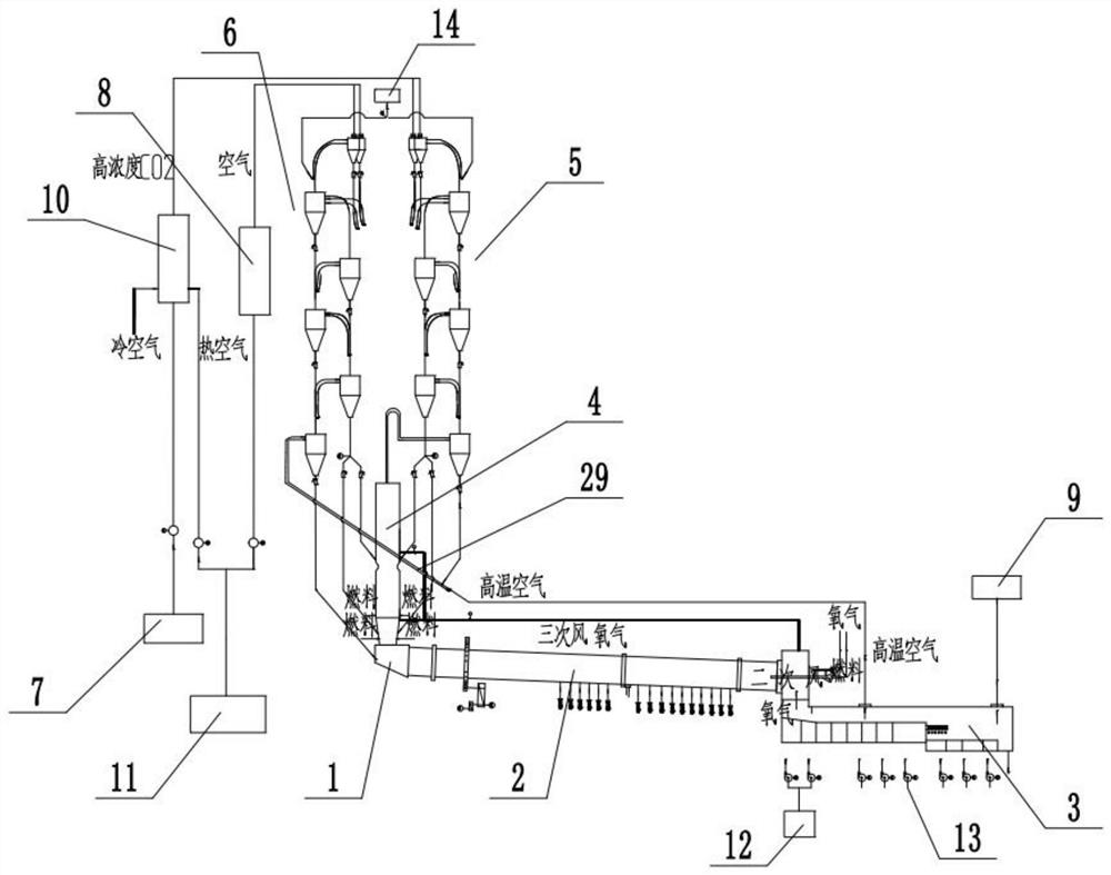
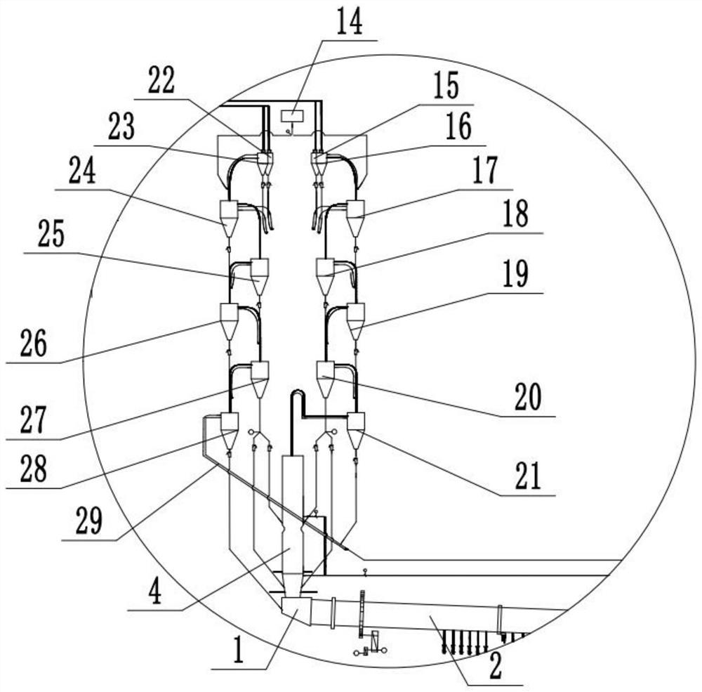
[0034] This embodiment provides a low CO 2 Partial pressure environment cement firing system, such as Figure 1 to Figure 2 As shown, it includes smoke chamber 1, rotary kiln 2, grate cooler 3, decomposition furnace 4, carbon dioxide capture and purification system 7, waste heat utilization system 8, independent multi-stage pure oxygen preheater 5 and multi-stage air preheater device 6; (refer to figure 1 with figure 2 , the left side is listed as multi-st...


PUM


Abstract

The invention discloses a low-CO2 partial pressure environment cement sintering system and a cement clinker preparation method, and belongs to the technical field of cement production equipment. The low-CO2 partial pressure environment cement sintering system comprises a smoke chamber, a rotary kiln, a grate cooler, a decomposing furnace, a carbon dioxide capturing and purifying system, a waste heat utilization system, a multi-stage pure oxygen preheater and a multi-stage air preheater, wherein the smoke chamber, the rotary kiln and the grate cooler are communicated in sequence; a high-temperature area of the grate cooler comprises a first cooling area and a second cooling area which are mutually independent, the first cooling area is communicated with the rotary kiln and a tertiary air pipe, and the second cooling area is communicated with the multi-stage air preheater through an air supply pipe; the multi-stage pure oxygen preheater is communicated with the decomposing furnace, the air supply pipe and the carbon dioxide capturing and purifying system; and the multi-stage air preheater is communicated with the decomposing furnace, the smoke chamber and the waste heat utilization system. A low-CO2-concentration and high-temperature low-CO2 partial pressure environment can be formed in the air supply pipe, hot raw materials can be further decomposed in the air supply pipe, and then the CaCO3 decomposition rate can be increased without increasing the temperature of the decomposing furnace.

Description

technical field [0001] The invention relates to the technical field of cement production equipment, in particular to a cement firing system in a low CO2 partial pressure environment and a cement clinker preparation method. Background technique [0002] The cement kiln firing system is generally used in the current cement production process. The cement kiln firing system is specifically composed of a cooler, a burner, a rotary kiln, a cyclone preheater, and a connecting air duct. Among them, the raw meal is preheated in the cyclone preheater and then decomposed in the calciner. Part of the fuel is burned in the calciner to provide the heat required for the decomposition of the raw meal. The decomposed hot raw meal is sent to the rotary kiln for another A part of the fuel is calcined and the hot raw meal is converted into cement clinker, and then the cement clinker is sent to the cooler, and the temperature is gradually reduced to an appropriate temperature under the cooling o...

Claims


Application Information

Patent Timeline
IPC IPC(8): F27B19/04F27D13/00F27D15/02F27D17/00C04B7/43C04B7/44C04B7/47
CPCF27B19/04F27D13/00F27D15/0213F27D17/004C04B7/432C04B7/44C04B7/475C04B7/47
Inventor 张超刘剑英王彬陶瑛邓玉华韩晓军曹新明申巧蕊姜斌
Owner CBMI CONSTR
Why Eureka
Try Eureka