Method for reducing residual stress of base material-additive body interface

A residual stress and base material technology, which is applied in the field of laser powder feeding additive manufacturing, can solve problems such as stress release deformation, base material deformation, and workpiece deformation, and achieve the effects of reducing stress concentration, reducing interface stress, and reducing deformation

Inactive Publication Date: 2021-12-03
CHENGDU AIRCRAFT INDUSTRY GROUP
View PDF7 Cites 2 Cited by
  • Summary
  • Abstract
  • Description
  • Claims
  • Application Information

AI Technical Summary

Problems solved by technology

[0003] However, due to the melting, accumulation and solidification of the substrate-additive body interface after laser beam scanning, there will be a significant temperature gradient with the substrate itself, which will inevitably form a huge residual stress, which will cause substrate deformation and even interface cracking. It will also cause deformation due to stress release during part processing
The existing technology mainly considers reducing the residual stress of the additive body itself. For example, the invention patent with the application number "CN202010238130.4" discloses "a repair path optimization method based on an in-situ stress release model", etc. There is still a lack of further measures to control the residual stress at the interface of the material body, which leads to defects such as deformation and cracking in the workpiece

Method used


Image

  • Method for reducing residual stress of base material-additive body interface
  • Method for reducing residual stress of base material-additive body interface
  • Method for reducing residual stress of base material-additive body interface

Examples


Embodiment 1

[0035] Such as Figure 1-6 As shown, this embodiment provides a method for reducing the residual stress at the substrate-additive body interface, comprising the following steps:

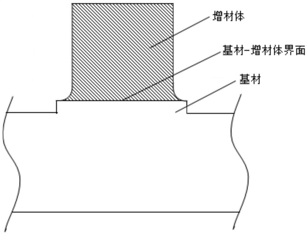
[0036] Step S1: In the substrate preparation stage, the substrate material around the substrate-additive body interface is removed to form a boss structure on the interface;

[0037] Step S2: Make the additive body grow on the boss structure, and design the transition area between the bottom of the additive body and the base material interface as a rounded transition structure, and then carry out additive manufacturing;

[0038] Step S3: Machining the substrate-additive body component.

[0039] In this embodiment, a surrounding unconstrained boss structure is constructed on the substrate corresponding to the additive manufacturing area, thereby reducing the extrusion and stretching of the surrounding materials during the laser scanning thermal expansion and cooling contraction of the substrate surfa...

Embodiment 2

[0058] Such as Figure 1-6 As shown, this embodiment is based on the specific embodiment of embodiment 1, and provides a method for reducing the residual stress at the substrate-additive body interface, including the following steps:

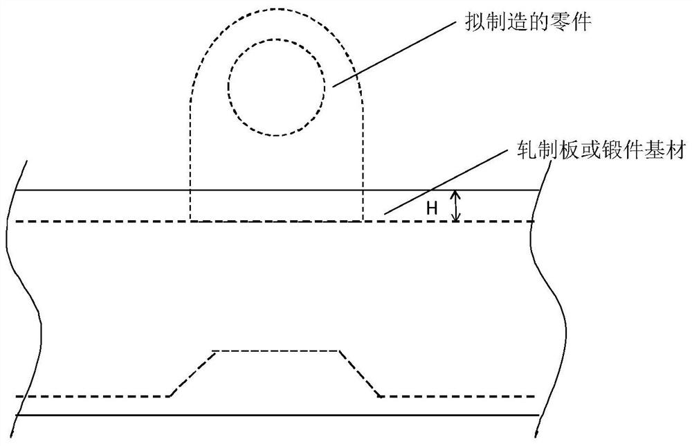
[0059] Step 1: Design the main stress-bearing part of the part in the area of ​​the forging or plate, select the specifications and dimensions of the rolled plate and forging base material according to the main structure of the part, and determine the machining allowance on the base material H = 10mm;

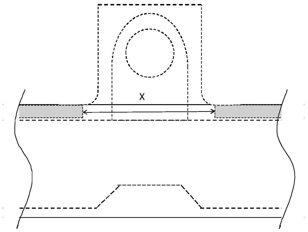
[0060] Step 2: The lugs of the part are processed by the additive body, the width of the ear piece is A=50mm, the machining allowance on the side of the additive body is W=6mm, the transition fillet radius of the substrate-additive body is R=5mm, and the additive body Projection size X=5mm+6mm+50mm+6mm+5mm=72mm;

[0061] Step 3: Outside the range of ±36mm from the center line of the lug, remove the base material with a thickness of h=5mm on the ...


PUM


Abstract

The invention discloses a method for reducing residual stress of a base material-additive body interface, and relates to the technical field of laser powder feeding additive manufacturing. The method comprises the following steps: S1, in a base material preparation stage, removing a base material on the periphery of the base material-additive body interface, and forming a boss structure on the interface; S2, enabling an additive body to grow on the boss structure, designing a transition region between the bottom of the additive body and a base material interface into a fillet transition structure, and then carrying out additive manufacturing; and S3, machining a base material-additive body part. The method has the beneficial effects that the residual stress of the base material-additive body interface in the laser additive manufacturing process can be reduced, and therefore the deformation and cracking tendency of the part is reduced.

Description

technical field [0001] The invention relates to the technical field of laser powder feeding additive manufacturing, in particular to a method for reducing the residual stress at the base material-add material interface. Background technique [0002] Laser simultaneous powder feeding additive manufacturing (also known as laser stereoforming) is a flexible manufacturing technology that can be used for rapid prototyping and damage repair. By spraying the metal powder on the surface of the metal substrate, and using the laser to melt the substrate and metal powder particles, the layer-by-layer accumulation is realized, and the shape of the accumulation is controlled by a computer program to form a part blank with a specific shape. Compared with traditional manufacturing technology, laser coaxial feeding additive manufacturing technology does not need to make additional molds, and the forming rate is higher than that of laser selective melting (SL) technology. Combining laser sy...

Claims


Application Information

Patent Timeline
Patent Type & Authority Applications(China)
IPC IPC(8): B22F10/25B22F10/80B33Y10/00B33Y40/10B22F12/30
CPCB22F10/25B22F10/80B33Y10/00B33Y40/10B22F12/30Y02P10/25
Inventor 虞文军王大为王少阳荣鹏唐维之
Owner CHENGDU AIRCRAFT INDUSTRY GROUP
Why Eureka
Try Eureka