
Low-nitrogen combustion method for radiant tube heating system

A technology of radiant tube heating and low-nitrogen combustion, which is applied in the direction of combustion methods, combustion control, and maintenance of heating chambers. It can solve the problems of large exhaust heat loss, limited combustion space, and high operating costs, and reduce the temperature of combustion flames. , reduce heat loss, and reduce investment costs

Pending Publication Date: 2021-12-03
CHONGQING CISDI THERMAL & ENVIRONMENTAL ENG CO LTD +1
View PDF4 Cites 0 Cited by
  • Summary
  • Abstract
  • Description
  • Claims
  • Application Information

AI Technical Summary

Problems solved by technology

In the radiant tube indirect heating system, the combustion space is severely limited and relatively closed, and the requirements for combustion technology are extremely high. Low-nitrogen combustion technologies such as conventional internal flue gas circulation / air gas staged combustion are difficult to adapt to, and the nitrogen reduction effect is very poor. Obviously; if the overall out-of-stock outside the furnace is used, there will be problems such as high operating costs
[0003] In the existing technology, the external circulation of flue gas is usually mixed with air to participate in combustion to achieve low nitrogen emission. However, the amount of external circulation of flue gas is not controlled, and there are technologies such as high exhaust temperature of the system and large exhaust heat loss. question

Method used


Image

  • Low-nitrogen combustion method for radiant tube heating system

Examples


Embodiment Construction

[0021] Embodiments of the present invention are described below through specific examples, and those skilled in the art can easily understand other advantages and effects of the present invention from the content disclosed in this specification. The present invention can also be implemented or applied through other different specific implementation modes, and various modifications or changes can be made to the details in this specification based on different viewpoints and applications without departing from the spirit of the present invention. It should be noted that the diagrams provided in the following embodiments are only schematically illustrating the basic concept of the present invention, and the following embodiments and the features in the embodiments can be combined with each other in the case of no conflict.

[0022] Wherein, the accompanying drawings are for illustrative purposes only, and represent only schematic diagrams, rather than physical drawings, and should...


PUM


Abstract

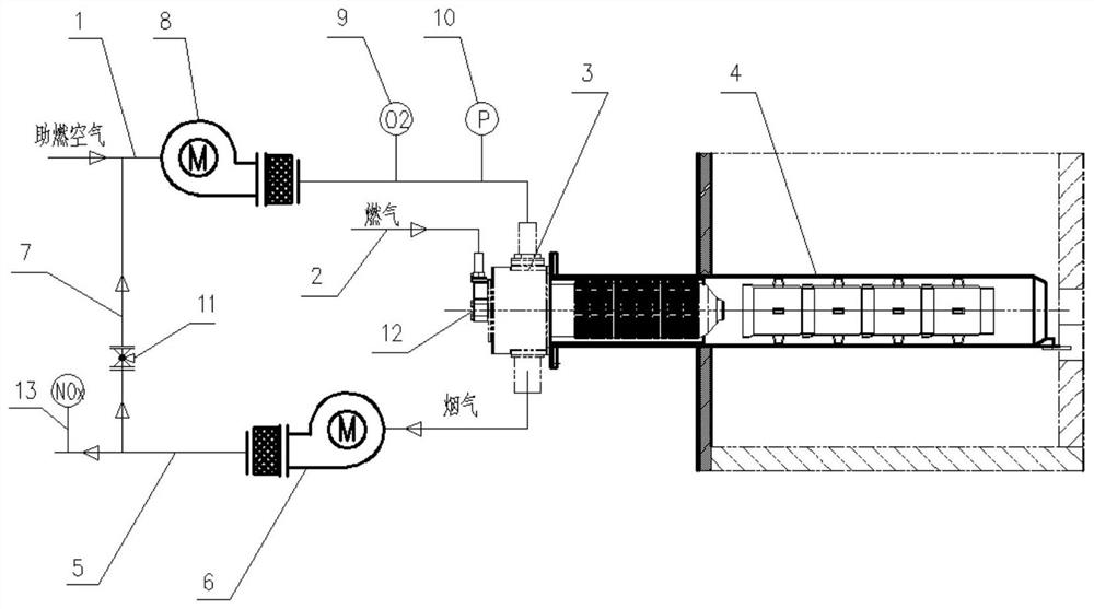
The invention relates to a low-nitrogen combustion method for a radiant tube heating system, and belongs to the technical field of low-nitrogen combustion, the air inlet end and the air outlet end of a radiant tube burner are connected with an air pipeline system and a smoke exhaust pipeline system respectively, and the smoke exhaust pipeline system is connected back to the air pipeline system through a flow regulating valve with a cut-off function. A NOx detection unit is arranged on the smoke exhaust pipeline system, an oxygen detection unit is arranged on the air pipeline system, a NOx emission target value is set, a combustion-supporting gas oxygen concentration set value is adjusted through a NOx detection value, and the opening degree of a flow adjusting valve with a cut-off function is adjusted through an oxygen detection value. Part of combustion waste gas enters the air pipeline system, the oxygen concentration of combustion-supporting air is reduced, the combustion intensity is reduced, and nitric oxides are reduced; and external flue gas circulation amount is controlled by the NOx detection value in a linkage manner, so that unnecessary increase of external flue gas circulation is avoided, and energy waste is reduced. The method can be widely applied to combustion systems with a high heat value, small combustion space, high heat intensity and high nitrogen oxide control difficulty.

Description

technical field [0001] The invention belongs to the technical field of low-nitrogen combustion, and relates to a low-nitrogen combustion method for a radiant tube heating system. Background technique [0002] In the heat treatment process of the steel production process, many links need to be carried out under a special furnace atmosphere, and radiant tubes must be used for indirect heating. In the radiant tube indirect heating system, the combustion space is severely limited and relatively closed, and the requirements for combustion technology are extremely high. Low-nitrogen combustion technologies such as conventional internal flue gas circulation / air gas staged combustion are difficult to adapt to, and the nitrogen reduction effect is very poor. Obviously; if the overall out-of-stock outside the furnace is used, there will be problems such as high operating costs. [0003] In the existing technology, the external circulation of flue gas is usually mixed with air to part...

Claims


Application Information

Patent Timeline
Patent Type & Authority Applications(China)
IPC IPC(8): F23N3/00F23N5/00C21D1/76F27D7/06
CPCF23N3/007F23N5/006C21D1/76F27D7/06F27D2007/063
Inventor 程奇伯王宏宇张道明芮州峰冯霄红雍海泉冯永生
Owner CHONGQING CISDI THERMAL & ENVIRONMENTAL ENG CO LTD
Learn More