Method and device for nondestructive testing of crystal orientation difference and grain boundary defects in single crystal or oriented crystal

A technology of crystal orientation and directional crystallization, which is applied in measuring devices, material analysis using radiation diffraction, instruments, etc., can solve the problems of long time consumption and no existing literature disclosure, etc., and achieve the effect of reliable crystal orientation

Pending Publication Date: 2021-12-03
NO 59 RES INST OF CHINA ORDNANCE IND
View PDF15 Cites 0 Cited by
  • Summary
  • Abstract
  • Description
  • Claims
  • Application Information

AI Technical Summary

Problems solved by technology

Of course, the orientation angle is measured position by position on the surface. According to the difference in the orientation angle of each position on the surface of the single crystal or oriented crystal body measured, the difference in the orientation angle of adjacent positions is greater than 10°. °~10° is a small-angle grain boundary to identify and determine grain boundary defects, and the difference in orientation angle is less than 2° is a ...

Method used


Image

  • Method and device for nondestructive testing of crystal orientation difference and grain boundary defects in single crystal or oriented crystal
  • Method and device for nondestructive testing of crystal orientation difference and grain boundary defects in single crystal or oriented crystal
  • Method and device for nondestructive testing of crystal orientation difference and grain boundary defects in single crystal or oriented crystal

Examples


Embodiment 1

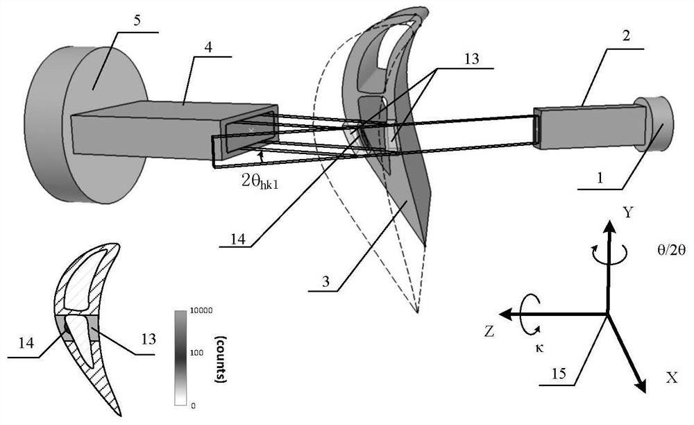
[0085] Example method for detecting the focus of this embodiment describes a single crystal inside a crystal orientation difference and the grain boundary defects lossless, in particular non-destructive testing internal γ crystal nickel-base superalloy blades' phase (200) plane orientation difference and the grain boundary defect.

[0086] In this embodiment diffractometer using a tungsten target X-ray tube, a tungsten target X-ray tube focal spot size of 5.5mm × 5.5mm, the selected diffraction WKα 1 Having a wavelength of 0.0209nm, the corresponding photon energy 59.3kev.

[0087] Wherein diffractometer:

[0088] The X-ray detection system is a single point detection system, and its energy resolution is superior to 2%;

[0089] The incident exclusion and receiving collimator are prepared by tungsten alloy material, the incident alignor and the receiving column light hole are rectangular light holes, and the height of the light hole and the shaft of θ and 2θ are parallel, and the l...

Embodiment 2

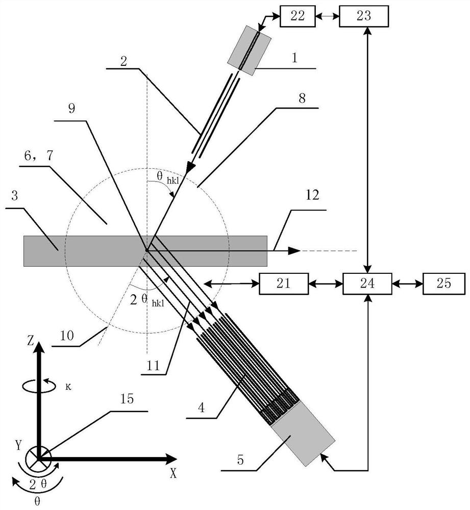
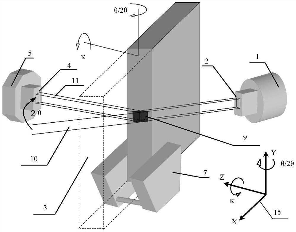
[0105] The present embodiment focuses on non-destructive detection directional crystals internal crystal orientation differences and grain boundary defects, specifically non-destructive detection of nickel-based high-temperature alloy directional crystal parts internal γ 'phase (200) crystal surface orientation difference and grain boundary defect.

[0106] In the present embodiment, the diffraction device is used with a tungsten target X-ray tube, and the tungsten target X-ray tube focus size is 0.4 mm × 0.4 mm, and WKα for diffraction is selected. 1 It has a wavelength of 0.0209 nm, and its corresponding photon energy is 59.3kev.

[0107] Among them, the diffractive device:

[0108] The X-ray detection system is an array detection system that includes a one-dimensional receiving array crimp and a two-dimensional array detector;

[0109] The inclusion and one-dimensional reception array crimp are prepared by heavy metals such as tungsten alloys and their alloy materials. The two-...

Embodiment 3

[0125] This embodiment focuses on non-destructive detection of hollow single crystal internal crystal orientation differences and grain boundle defects, specifically non-destructive detection of the internal γ 'phase (420) crystal surface orientation difference between the nickel-based high-temperature alloy hollow single crystal cross section and the grain boundary defect.

[0126] The method and apparatus employed in this example refer to Example 2, which is the main difference from Example 2 in:

[0127] The sample was measured as a nickel-based high-temperature alloy hollow single crystal sample;

[0128] Added a diffraction intensity correction method;

[0129] Each parameter is different: the present embodiment uses the gold target X-ray tube as a radiation source, its focus size is 5.5mm × 5.5mm, and the diffraction is used for Aukα 1 The wavelength is 0.0180 nm, and its corresponding photon energy is 68.794 Kev, γ '- (420) diffraction angle 2θ of the crystal plane 420 = 12...


PUM


Abstract

The invention provides a method and device for nondestructive testing of crystal orientation difference and grain boundary defects in a single crystal or oriented crystal. The method comprises the following steps of: carrying out nondestructive testing of a crystal orientation angle (theta1, kappa1) of a crystal face in a certain direction (h1k1l1) in a sample by adopting transmission short-wavelength characteristic X-ray diffraction, and determining whether the orientation angle of the crystal face of the sample is out of tolerance or not; and in the (theta1, kappa1) direction of the crystal face, translating the sample, scanning and measuring the diffraction intensity and distribution of the (h1k1l1) crystal face of each part of the tested sample, and judging whether a grain boundary defect and a sub-grain boundary defect exist in the tested sample or not according to a measurement result. The device comprises a sample table, an X-ray irradiation system, an X-ray detection system, a rotating mechanism and the like, wherein the rotating mechanism is used for changing an included angle between an incident X-ray beam and a sample. With the method adopted, the problem that crystal defects such as crystal orientation difference, sub-grain boundary and grain boundary in the single crystal and the oriented crystal cannot be quickly, accurately and nondestructively measured is solved.

Description

Technical field [0001] The present invention relates to a non-destructive detection technique of crystalline defects, and more particularly to non-destructive detection of single crystals or methods and apparatus for unity and grain boundary defects of single crystals or directional crystals. Background technique [0002] The internal defects of single crystals and directional crystals are usually divided into two major categories, and one is a deficiencies such as air holes, inclusion, and the other is crystal alignment angles, crystal defects such as grain boundaries. For the former, it is usually used to non-destructive inspection materials / workpiece, which detects the X-ray absorption coefficient of different positions of the material / workpiece, and its distribution according to X-ray absorption coefficients. Differentially determines the pores, inclusions, etc. For the latter, a cut-cut single crystal is usually used, and the tie crystal is or corroded. It is detected wh...

Claims


Application Information

Patent Timeline
IPC IPC(8): G01N23/20G01N23/20008
CPCG01N23/20G01N23/20008
Inventor 郑林窦世涛张津车路长陈新封先河唐伦科张伦武王成章伍太宾赵方超何长光
Owner NO 59 RES INST OF CHINA ORDNANCE IND
Why Eureka
Try Eureka