
Adsorption concentration runner blast furnace gas desulfurization system and method thereof

A technology of concentrating runner and desulfurization system, which is applied in the selection of absorbing solid gas purification, combustible gas purification, and removal of gas pollutants, etc., can solve the problem of reduced hydrolysis efficiency and life, increased equipment footprint, Catalyst damage and other problems, to achieve the effect of reducing equipment size, reducing investment, and simplifying the process of desulfurization

Pending Publication Date: 2021-12-07
BEIJING SHOUGANG INT ENG TECH
View PDF0 Cites 0 Cited by
  • Summary
  • Abstract
  • Description
  • Claims
  • Application Information

AI Technical Summary

Problems solved by technology

Blast furnace gas volume is large, reaching 400,000Nm 3 / h, the sulfide content is 200ppm, and it also contains other components, which may cause fatal damage to the catalyst when entering the hydrolysis tower, resulting in a reduction in hydrolysis efficiency and life. It is understood that the main problem in the application of this process is catalyst life and efficiency. problem; and such a large gas volume will inevitably increase the equipment footprint, and because the gas contains a large amount of carbon dioxide, most of the alkali in the process of absorbing hydrogen sulfide by alkali spraying actually reacts with carbon dioxide, and only a small part is used. Absorb hydrogen sulfide, resulting in a large amount of lye waste and the formation of a large amount of waste water, resulting in secondary pollution

Method used


Image

  • Adsorption concentration runner blast furnace gas desulfurization system and method thereof

Examples


Embodiment 1

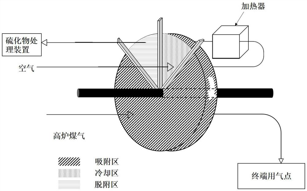
[0029] As shown in the figure, the enrichment rotor is filled with activated carbon adsorbent modified by alkali metal, blast furnace gas (containing CO 2 , CO, COS, H 2 , H 2 S, where COS stands for organic sulfur) is introduced into the concentrating runner and adsorbed in the adsorption zone. The clean gas after adsorption enters the pipe network to reach the gas consumption point. The concentrating runner rotates clockwise at a rate of 8r / min. Adsorption in the adsorption area is completed, and the rotor is transferred to the desorption area. The hot air blowing at 500°C in the desorption area will desorb the sulfide, and bring it to the direct combustion incinerator, ignite and burn the sulfide to generate sulfur dioxide, and then use SDS to dry it. The desulfurization system removes sulfur dioxide, and the desorbed adsorbent comes to the cooling area with the rotation of the runner, and is regenerated after being purged and cooled by air, where it can enter the adsorpti...

Embodiment 2

[0031] As shown in the figure, the enrichment rotor is filled with alkali metal modified alumina adsorbent, blast furnace gas (containing CO 2 , CO, COS, H 2 , H 2S, where COS stands for organic sulfur) is introduced into the enrichment runner, and is adsorbed in the zone, and the clean gas after adsorption enters the pipeline network to reach the gas point, the enrichment runner rotates clockwise at a rate of 15r / min, and the adsorbent is After the adsorption zone is completed, the rotor is transferred to the desorption zone. The sulfide is desorbed by hot air blowing at 700°C in the desorption zone and brought to the catalytic oxidizer, where the sulfide is catalyzed and oxidized into sulfur dioxide, and then the CFB semi-dry desulfurization system is used. Sulfur dioxide is removed, and the desorbed adsorbent comes to the cooling area with the rotation of the runner, and is regenerated after being purged and cooled by air, and can play the function of adsorbing sulfide whe...

Embodiment 3

[0033] As shown in the figure, the concentration runner is filled with ZSM-5 molecular sieve adsorbent, blast furnace gas (containing CO 2 , CO, COS, H 2 , H 2 S, where COS stands for organic sulfur) is introduced into the enrichment runner, and is adsorbed in the adsorption zone. After the adsorption, the clean gas enters the pipeline network to reach the gas consumption point, and the enrichment runner rotates clockwise at a rate of 6r / min. After the adsorption in the adsorption zone is completed, the rotor turns to the desorption zone. The hot air blowing at 400°C in the desorption zone desorbs the sulfides and takes them to the regenerative catalytic oxidizer, where the sulfides are catalyzed and oxidized into sulfur dioxide, and then lime / The gypsum desulfurization system removes sulfur dioxide, and the desorbed adsorbent comes to the cooling zone with the rotation of the runner, and is regenerated after being purged and cooled by air, and can play the function of adsor...


PUM


Abstract

The invention discloses an adsorption concentration runner blast furnace gas desulfurization system and a method thereof, and belongs to blast furnace gas treatment technology in metallurgical industry. The system can solve the problems of long desulfurization process and large occupied space in the prior art. The desulfurization system comprises an adsorption and concentration rotating wheel and a sulfide treatment device, the concentration rotating wheel in the desulfurization system is divided into a plurality of areas, including an adsorption area, a desorption area and a cooling area, and sulfides in coal gas are adsorbed in the adsorption area and enter the sulfide treatment device after being desorbed in the desorption area; the adsorbent subjected to hot air desorption reaches the cooling area to be cooled and then reaches the adsorption area to play an adsorption function again; and according to the desulfurization system, the sulfides are concentrated and intensively treated, the desulfurization process is simplified, the energy consumption for treating the sulfides is reduced, the use of desulfurization reagents is reduced, the scale of required equipment is greatly reduced by purely treating the sulfides, the occupied field area is reduced, and the desulfurization system has the advantages of economy, high efficiency, environmental protection and the like.

Description

technical field [0001] The invention relates to blast furnace gas treatment technology in the metallurgical industry, in particular to an adsorption concentration runner blast furnace gas desulfurization system. Background technique [0002] Blast furnace gas is a by-product flammable gas in the ironmaking process, and is usually used as fuel for hot blast stoves, heating furnaces, and boilers, and is an available resource. Blast furnace gas contains H 2 , CO 2 , CO, CH 4 In addition, it also contains impurities such as sulfide, a small amount of chlorine and dust. Usually the blast furnace gas is sent to the downstream terminal for combustion after dedusting and purification. During the combustion process, the sulfide in the gas will produce sulfur dioxide. If the sulfur dioxide is not treated, it will cause serious air pollution. In 2019, five ministries including the Ministry of Ecology and Environment, the National Development and Reform Commission, and the Ministry ...

Claims


Application Information

Patent Timeline
IPC IPC(8): C10K1/22C10K1/26C10K1/32
CPCC10K1/22C10K1/26C10K1/32C10K1/004
Inventor 田向乐王森林
Owner BEIJING SHOUGANG INT ENG TECH
Learn More