Forming method for electric arc fuse wire additive manufacturing

An additive manufacturing and fuse technology, applied in the field of additive manufacturing, can solve problems such as the relationship and research of magnetic and magnetron-assisted arc fuses that are not involved, and improve the forming morphology and internal structure, and the surface of the weld bead is flat. Smooth, Manufacturing Efficiency Effects

Active Publication Date: 2021-12-17
HUAZHONG UNIV OF SCI & TECH
View PDF12 Cites 1 Cited by
  • Summary
  • Abstract
  • Description
  • Claims
  • Application Information

AI Technical Summary

Problems solved by technology

Fixed magnetic field limits complex configurations for arc fuse additive manufacturing
Moreover, there is currently no research on the relationship and research on the relationship between the magnetism in the product and the additive manufacturing of magnetron-assisted arc fuses.

Method used


Image

  • Forming method for electric arc fuse wire additive manufacturing
  • Forming method for electric arc fuse wire additive manufacturing
  • Forming method for electric arc fuse wire additive manufacturing

Examples


Embodiment 1

[0040] This embodiment provides a forming method for arc fuse additive manufacturing, which is used to form arc fuse additive manufacturing for 316L stainless steel, including the following steps:

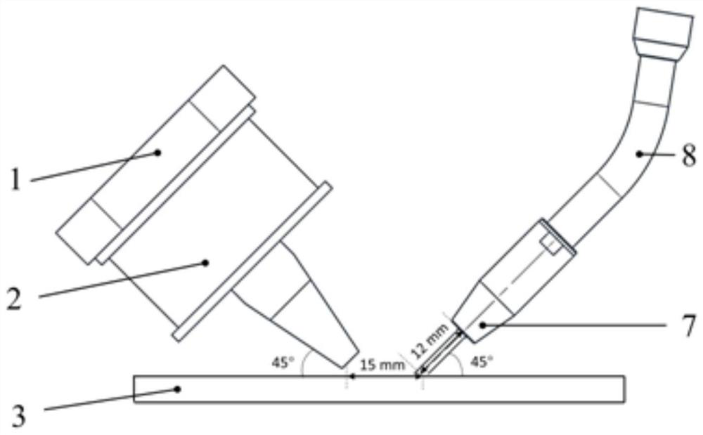
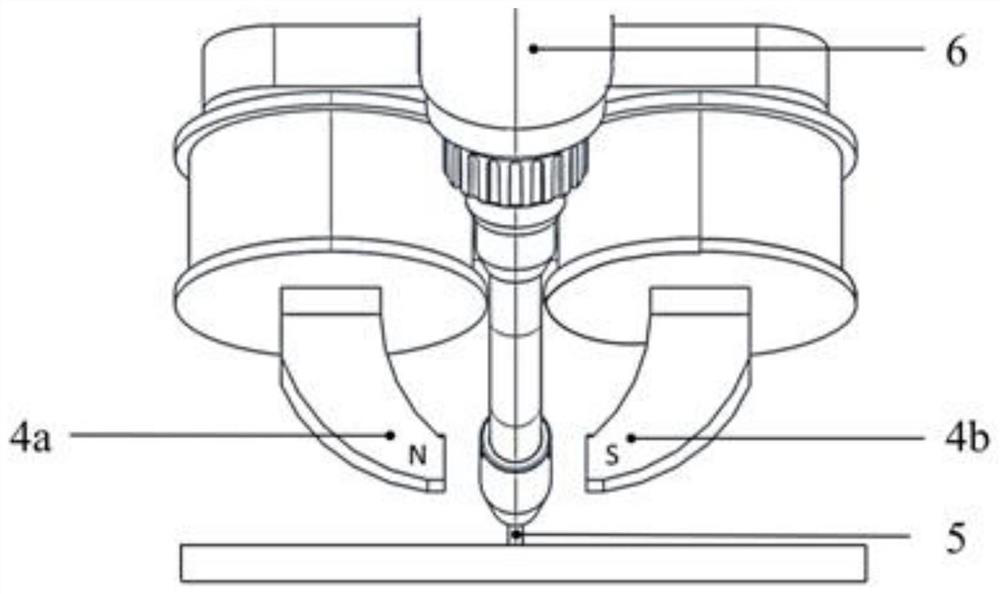
[0041] S1 Clamp the 316L stainless steel substrate 3 on the working platform, fix the clamp type electromagnet device and the arc welding torch device through the tooling fixture, set the dry elongation 5 of the welding wire to 1.2cm, and control the horizontal distance between the end point of the welding wire and the center of the magnetic pole 4 to 20mm , The inclination angle of the arc torch is 45°, and the inclination angle of the magnetic pole is 135°.

[0042] S2 Set the excitation current to 1.5A and the voltage to 7.45V on the panel of the DC excitation power supply, corresponding to the magnetic field strength at the end point of the welding wire at 20.7mT, and check the magnetic field strength at the end point of the welding wire and the direction of the magnetic inducti...

Embodiment 2

[0048] This embodiment provides a forming method for arc fuse additive manufacturing, which is used to form arc fuse additive manufacturing for 30CrMnSiNi2A high-strength steel (30Cr), including the following steps:

[0049] S1 Preheat the 30CrMnSiNi2A substrate to 300°C, then clamp it on the working platform, fix the clamp-type electromagnet device and the arc welding torch device through the tooling fixture, set the dry elongation of the welding wire to 1.2cm, and control the end point of the welding wire and the magnetic pole The horizontal distance between the 4 centers is 15mm, the inclination angle of the arc torch is 30°, and the inclination angle of the magnetic pole is 120°.

[0050] S2 Set the excitation current on the DC excitation power panel to 4A, the voltage to 18.18V, corresponding to the magnetic field strength at the end point of the welding wire at 59.6mT, and check the magnetic field strength at the end point of the welding wire and the direction of the magn...

Embodiment 3、 comparative example 1

[0055] Embodiment 3, comparative example 1, comparative example 2

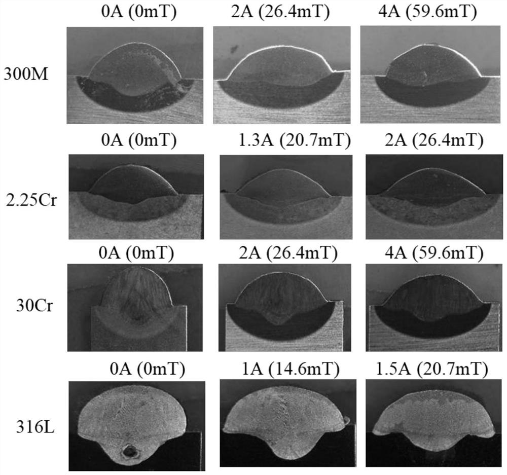
[0056] These comparative examples and examples adopt the same method as Example 1, the difference is that the applied transverse magnetic field has different magnetic field strengths at the end of the welding wire, specifically see Table 1 below:

[0057] Table 1-316L stainless steel arc fuse additive manufacturing magnetic field strength table

[0058]

[0059] It should be noted that the weld bead corresponding to the excitation current of 2A in Comparative Example 2 has poor morphology and high surface roughness, which is mainly due to the increase in arc instability observed during the additive process. As the excitation current continues to increase, the forward deflection angle of the arc column increases, causing an increase in the amount of spatter.


PUM

PropertyMeasurementUnit
magnetic flux densityaaaaaaaaaa
diameteraaaaaaaaaa
magnetic flux densityaaaaaaaaaa

Abstract

The invention discloses a forming method for electric arc fuse wire additive manufacturing. The method comprises the steps that a clamp type electromagnet and an electric arc welding gun are fixed to a robot, different inclination angles exist between the clamp type electromagnet and a workpiece substrate and between the electric arc welding gun and the workpiece substrate, and electric arc fuse wire additive manufacturing is conducted under a steady transverse magnetic field generated by the clamp type electromagnet; wherein the magnetic field intensity of the transverse magnetic field is adjusted according to the magnetism of a finally-formed product, so that welding seam forming is improved, the internal air hole defect is reduced, internal crystal grains are refined, and element segregation is restrained; and the optimal magnetic field intensity of the transverse magnetic field is positively correlated with the magnetism of the finally-formed product. Residual stress distribution is optimized, the micro air hole defect is reduced or eliminated, heat dissipation of a molten pool is promoted, a welding seam structure is refined, element segregation is inhibited, and the mechanical property and corrosion resistance of an electric arc additive component are comprehensively improved. The magnetic field intensity of the transverse magnetic field is adjusted according to the magnetism of the finally-formed product, and the research blank in the aspect is filled up.

Description

technical field [0001] The invention belongs to the technical field of additive manufacturing, and more particularly relates to a forming method for arc fuse additive manufacturing. Background technique [0002] The arc fuse additive manufacturing technology uses the arc as the heat source to melt the alloy wire, and based on the cold metal transition process, according to the slicing algorithm of the 3D model and the trajectory of the robot, it is a kind of layer-by-layer additive forming from 2D to 3D. Advanced Manufacturing Technology. Compared with laser and electron beam additive manufacturing, the efficiency of arc fuse additive manufacturing is higher, and it breaks through the limitation of confined space protection, and highlights the advantages of high efficiency and low cost when forming large-sized and complex components. [0003] At present, the arc fuse additive manufacturing technology has been applied in stainless steel, die steel, high-strength steel, alumi...

Claims


Application Information

Patent Timeline
Patent Type & Authority Applications(China)
IPC IPC(8): B23K9/04B23K9/08B23K9/32B23K9/16
CPCB23K9/044B23K9/08B23K9/32B23K9/16Y02P10/25
Inventor 郑志镇仲杨李建军张良伟张华
Owner HUAZHONG UNIV OF SCI & TECH
Why Eureka
Try Eureka