Supercharge Your Innovation With Domain-Expert AI Agents!

Kiln for producing high-quality photovoltaic glass and novel calendering forming overflow opening

A calendering and photovoltaic glass technology, which is applied in glass furnace equipment, furnace types, glass production, etc., can solve the problems of high glass edge loss rate at the forming part, uneven glass thickness, and high intermediate temperature, so as to facilitate calendering and forming control , the effect of reducing glass bubble defects and reducing the temperature difference of glass liquid

Pending Publication Date: 2021-12-24
SIPING HONGDA HYDRAULIC MECHANICAL MFG CO LTD
View PDF3 Cites 2 Cited by
  • Summary
  • Abstract
  • Description
  • Claims
  • Application Information

AI Technical Summary

Problems solved by technology

[0006] First, the temperature difference between the overflow outlets of each branch channel is large
The length of the above-mentioned single branch channel is too long, and the length of the middle branch channel is different from that of the outer branch channel, resulting in a large temperature difference at the outlet of each branch channel, which brings difficulties to the glass calendering process.
[0007] Second, there is a large temperature difference in the lateral glass liquid at the overflow outlet of the same branch
As a result, when the molten glass flows to the overflow port, the temperature of the molten glass on both sides of the overflow port is low and the temperature in the middle is high, which leads to uneven thickness of the glass plate produced when the molten glass of the same branch line passes through the forming calender. The difference is large, and the thickness is extremely poor, which cannot meet the 0.25mm requirement standard of the photovoltaic glass industry
[0008] Third, under the same drawing amount, the more branch channels are set, the smaller the drawing amount of each branch channel single line is, the narrower the width of the calendered overflow outlet brick is, and the loss of edge cleaning of the glass at the forming part The higher the rate, the lower the yield
The greater the investment in fixed assets for equipment
[0010] Fifth, in the horizontal passage, the surface flow of the glass liquid flow is from front to back, while the backflow of the bottom layer of the glass liquid is from back to front, such as figure 1 The floor plan of the glass liquid backflow, where the glass liquid flows in different directions meet, it is easy to generate air bubbles
There will be a certain amount of cold glass fluid in the gap between the lip brick and the inner tail brick, and the cold glass here must be cleaned every time the lip brick is replaced. The larger the contact area between the lip brick and the inner tail brick, the more cold glass will accumulate. The process of cleaning the cold glass is complicated, and the inner tail brick will be damaged when cleaning the cold glass liquid. At this time, the inner tail brick must be replaced regularly
The replacement of the inner tail brick needs to lift the flame block of the furnace. At this time, the flames in the furnace overflow. Therefore, the workload of replacing the inner tail brick is very heavy.
[0013] For this reason, the ultra-clear calendered glass kiln and calendered overflow in the prior art produce glass with uneven thickness, narrow glass plate width (less than or equal to 3300mm), high edge loss rate, and high production line investment cost , the produced glass has many defects, and at the same time, the replacement of the tail brick structure in the overflow port at the end of the melting furnace is time-consuming and laborious, resulting in large production losses and high costs

Method used


Image

  • Kiln for producing high-quality photovoltaic glass and novel calendering forming overflow opening
  • Kiln for producing high-quality photovoltaic glass and novel calendering forming overflow opening
  • Kiln for producing high-quality photovoltaic glass and novel calendering forming overflow opening

Examples


Embodiment Construction

[0049] In order to solve the defects pointed out in the background art, the present invention is specially applied for. The present application will now be described more fully with reference to the accompanying drawings, in which example embodiments are shown. However, the invention should not be construed as limited to the embodiments set forth herein. The disclosed features of the example embodiments may be combined as is readily understood by a person skilled in the art to which this application pertains. Well-known functions or constructions are not described in detail in this application for brevity or clarity.

[0050] The application is described in detail below in conjunction with accompanying drawing:

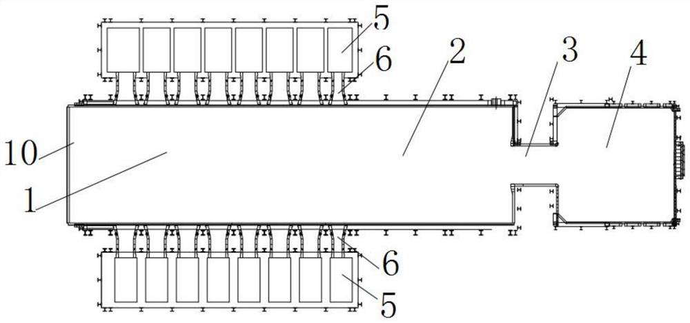
[0051] like image 3 , Figure 4 As shown, the embodiment of the present invention provides an ultra-large-tonnage ultra-clear glass furnace for producing high-quality photovoltaic glass, with a daily melting capacity of more than 1,100 tons. It includes a meltin...


PUM

PropertyMeasurementUnit
widthaaaaaaaaaa

Abstract

The invention relates to a kiln for producing high-quality photovoltaic glass and a novel calendaring overflow port. The kiln comprises a kiln tank, the kiln tank comprises a melting part, a clarifying part, a neck and a transverse passage which are sequentially communicated, and the tail end of the transverse passage is directly connected with an overflow port. According to the kiln with the structure, a branch passage is not arranged behind the transverse passage, and the transverse passage is directly connected with the overflow port, so that the phenomena of low temperature of molten glass at the overflow port, high intermediate temperature and large transverse temperature difference caused by an overlong branch passage in the prior art are reduced; and the liquid flow fluctuation caused by excessive turning of the branch passage is avoided, so that the bubble defect of the glass is favorably reduced. According to the kiln structure disclosed by the invention, the transverse passage is directly connected with one or more overflow ports, the temperature difference of molten glass of each overflow port is small, and the forming temperature at a calendaring forming part is basically consistent, so that the forming control of glass is facilitated.

Description

technical field [0001] The invention relates to the field of glass production equipment, in particular to a kiln for producing high-quality photovoltaic glass and a novel calendering overflow port. Background technique [0002] In 2020, the Chinese government put forward China's commitment to the world at the Davos Forum, advocating green and low-carbon. Achieve carbon peak in 2030 and achieve carbon neutrality in 2060. The carbon emission of photovoltaic power generation is one-tenth to one-twentieth of that of fossil energy power generation. It is a real low-carbon energy source, but photovoltaic power generation currently only accounts for 3.5% of my country's power generation. Photovoltaic will gradually become one of the important power sources in China in the future, providing a strong engine for the realization of "carbon peak" and "carbon neutrality". [0003] Photovoltaic glass, one of the important components of photovoltaic power generation, is also constantly i...

Claims


Application Information

Patent Timeline
Patent Type & Authority Applications(China)
IPC IPC(8): C03B5/04C03B5/26C03B7/02
CPCC03B5/04C03B5/265C03B7/02Y02P40/57
Inventor 单晓义单泰宏王威
Owner SIPING HONGDA HYDRAULIC MECHANICAL MFG CO LTD
Features
  • R&D
  • Intellectual Property
  • Life Sciences
  • Materials
  • Tech Scout
  • Unparalleled Data Quality
  • Higher Quality Content
  • 60% Fewer Hallucinations
Learn More