Centralized cell sorting system and sorting method
A sorting system and cell technology, applied in the field of cell sorting, can solve the problems of increased analysis time and cost, increased volume of recovered liquid, loss of precious samples, etc., so as to reduce analysis costs, improve efficiency, and avoid cell loss and damage. Effect
- Summary
- Abstract
- Description
- Claims
- Application Information
AI Technical Summary
Problems solved by technology
Method used
Image

Examples
Embodiment 1
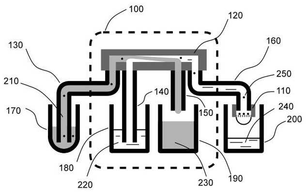
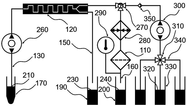
[0078] This embodiment provides a centralized cell sorting system, such as Figure 1-Figure 4 As shown, it includes a microfluidic cell sorting device 120 for enriching target cells 250 in a cell suspension sample containing target cells 250, and a first driver for driving the cell suspension sample into the microfluidic cell sorting device 120 mechanism; the microfluidic cell sorting device 120 is provided with a pipeline A150 for the sample waste liquid 230 to flow out and a pipeline B160 for the target cell 250 to flow out; Pore filter device 110.
[0079] Specifically, the first driving mechanism may be a peristaltic pump, a syringe pump, a diaphragm pump, a gear pump, a plunger pump, an electroosmotic pump, etc., which are used to drive the cell suspension into the microfluidic cell sorting device 120 .
[0080] The microfluidic cell sorting device removes most of the non-target cells and other particulate components in the cell suspension sample, reducing and avoiding...
Embodiment 2
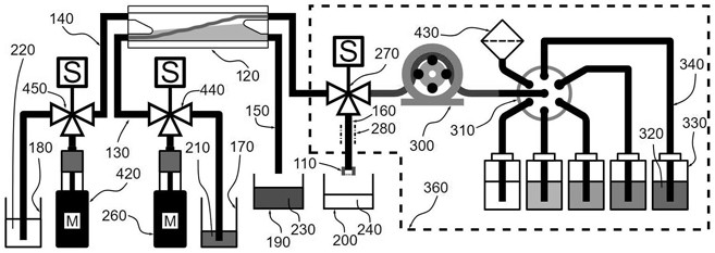
[0109] This embodiment provides a centralized cell sorting system, such as Figure 4 as shown, Figure 4 for figure 2A more specific implementation of the system shown is used to illustrate another possible presentation of the system when different types of component functional units are used. Including the pretreatment system 100 and the second device 360, wherein the microfluidic cell sorting device 120 can further be a spiral flow channel inertial focus microfluidic chip; the spiral flow channel inertial focus microfluidic chip includes a plurality of spirally arranged flow One end of the flow channel includes an inlet C for the input of the diluted cell suspension sample, and the other end includes an outlet D; the outlet D includes at least two channels, one of which is for target cells and buffer to flow out, and the other for samples Waste liquid outflow; in a specific application, the flow ratio of the sample waste liquid after flowing out of the spiral flow channel...
Embodiment 3
[0126] The present invention also includes a cell sorting method, using the above-mentioned centralized cell sorting system; such as Figure 6 As shown, which includes the following steps:
[0127]Step 1: introduce the cell suspension sample containing target cells into the microfluidic cell sorting device through the sample injection pipeline, and remove the main non-target particle components through the microfluidic cell sorting device;
[0128] Step 2: introduce the sorted cell suspension sample in step 1 into the microporous membrane device along the fixed flow channel, and the microporous membrane device filters out some non-target particle components and waste liquid, and simultaneously The target cells are trapped in the microporous membrane device to complete the sorting;
[0129] Step 3: separating the microporous membrane device containing the target cells retained in step 2 from the fixed channel.
PUM
 Abstract
Description
Claims
Application Information
PatSnap Eureka turns technology decisions into work you can execute. Powered by our Innovation Knowledge Graph, it runs expert workflows across engineering, life sciences, materials and intellectual property. Get your review-ready output in minutes.


