
Digital scanning rod, tool for machining and machining method

A scanning rod and tooling technology, which is applied in metal processing equipment, used abrasive processing devices, manufacturing tools, etc., can solve the problems of uneven powder spray thickness, affecting scanning accuracy, and affecting scanning results, etc., to achieve low cost, The effect of uniform surface and guaranteed precision

Pending Publication Date: 2022-01-18
郑州康德泰口腔医疗科技有限公司
View PDF6 Cites 0 Cited by
  • Summary
  • Abstract
  • Description
  • Claims
  • Application Information

AI Technical Summary

Problems solved by technology

[0003] At present, there are two types of scanning rods, the first one is a scanning rod made of polyether ether ketone (PEEK), and the second one is a scanning rod made of metal material. When using it, it is necessary to spray powder on the surface. The purpose of powder spraying is to Cover the metal glossy surface to avoid reflection and affect the scanning results
[0004] The raw material of the scanning rod made of polyether ether ketone (PEEK) is plastic parts, and the processing accuracy is relatively low; the scanning rod made of metal material needs to be sprayed with powder before each use, and needs to be cleaned to remove the powder after use. The powder is sprayed in the patient's mouth during powder spraying It will cause discomfort to the patient, and the thickness of the sprayed powder will be uneven, which will affect the scanning accuracy

Method used


Image

  • Digital scanning rod, tool for machining and machining method
  • Digital scanning rod, tool for machining and machining method
  • Digital scanning rod, tool for machining and machining method

Examples


Embodiment Construction

[0033] It should be noted that, in the case of no conflict, the embodiments of the present invention and the features in the embodiments can be combined with each other.

[0034] In describing the present invention, it should be understood that the terms "center", "longitudinal", "transverse", "upper", "lower", "front", "rear", "left", "right", " The orientations or positional relationships indicated by "vertical", "horizontal", "top", "bottom", "inner" and "outer" are based on the orientations or positional relationships shown in the drawings, and are only for the convenience of describing the present invention and Simplified descriptions, rather than indicating or implying that the device or element referred to must have a particular orientation, be constructed and operate in a particular orientation, and thus should not be construed as limiting the invention. In addition, the terms "first", "second", etc. are used for descriptive purposes only, and should not be understood ...


PUM


Abstract

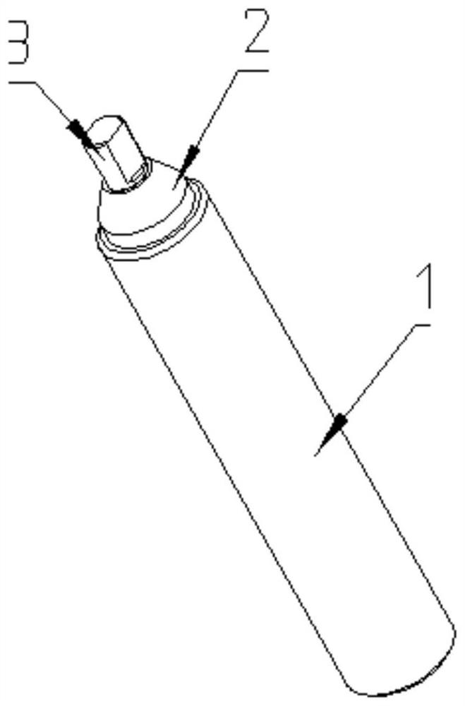
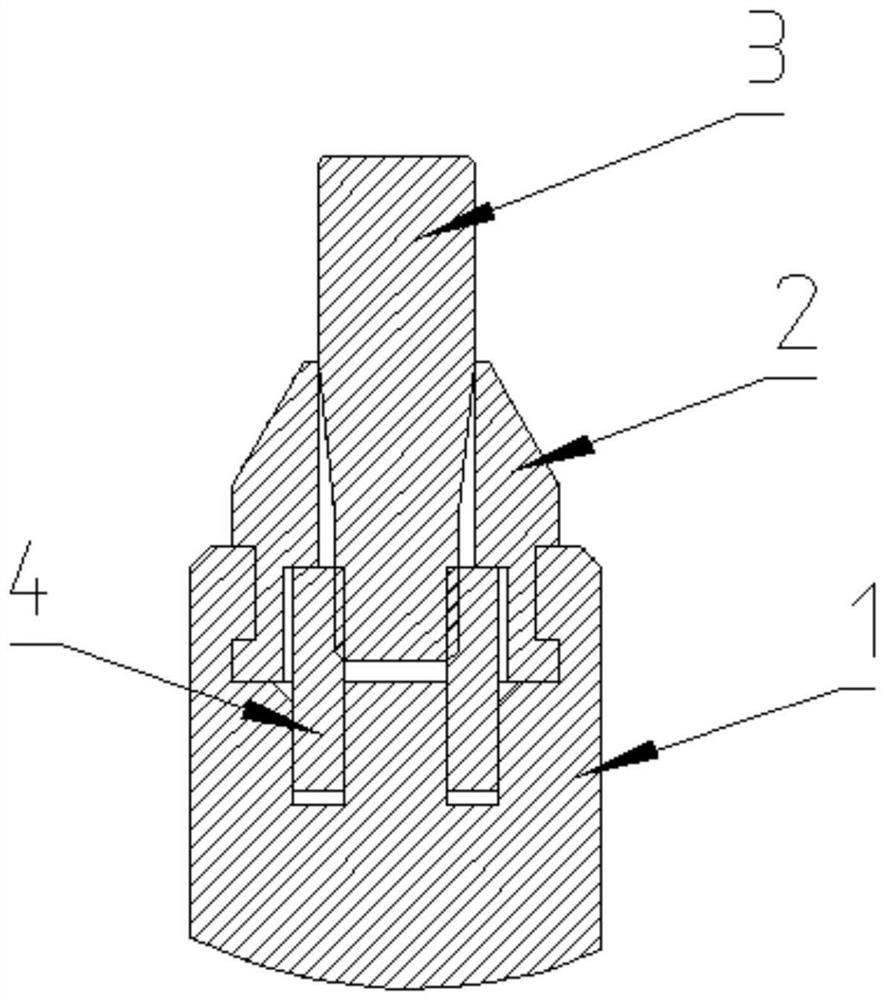
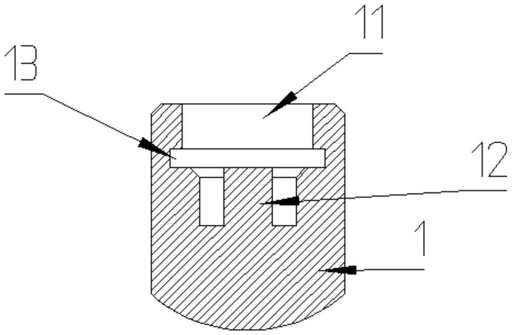
The invention provides a digital scanning rod, a tool for machining and a machining method, and belongs to the field of oral cavity medical equipment. The digital scanning rod comprises a cylindrical section, a conical section and a connecting section which are sequentially arranged from bottom to top and are coaxial, a sand blasting layer is arranged on the outer surface of the connecting section, and the connecting section is made of stainless steel, pure titanium and titanium alloy. The machining method comprises the following steps: firstly inserting the scanning rod into an elastic sleeve in the tool along an inner hole of a limiting sleeve; secondly, clamping a handle part on sand blasting equipment so as to clamp the handle; thirdly, setting sand blasting parameters on an automatic sand blasting machine; fourthly, taking the tool down from the sand blasting machine, and taking a product down from the tool; fifthly, grinding to remove floating sand on the surface; and sixthly, drying after cleaning, and removing grinding fluid on the surface of the product. A metal product surface sand blasting process is adopted, the product machining precision is guaranteed, it can be guaranteed that the surface does not reflect light, powder spraying operation is not conducted in the oral cavity of a patient, the patient does not feel uncomfortable, and the surface is uniform.

Description

technical field [0001] The invention belongs to the field of oral medical equipment and relates to dental implant surgery, in particular to a digital scanning rod, tooling for processing and a processing method. Background technique [0002] For the accuracy of personalized restoration of tooth loss, many hospitals use digital restoration technology to help doctors determine the position of implant placement during surgery, which facilitates the design of restorations and requires the use of scanning rods. [0003] At present, there are two types of scanning rods, the first one is a scanning rod made of polyether ether ketone (PEEK), and the second one is a scanning rod made of metal materials. When using it, it is necessary to spray powder on the surface. The purpose of powder spraying is to Cover up the metal glossy surface to avoid reflection and affect the scanning results. [0004] The raw material of the scanning rod made of polyether ether ketone (PEEK) is plastic pa...

Claims


Application Information

Patent Timeline
IPC IPC(8): A61C8/00B24C9/00B24C1/06B24B1/00B24B27/033B24B55/06
CPCA61C8/0089B24C9/00B24C1/06B24B27/033B24B1/005B24B55/06Y02E30/30
Inventor 黄利伟徐海锋赵攀杨楠
Owner 郑州康德泰口腔医疗科技有限公司
Learn More