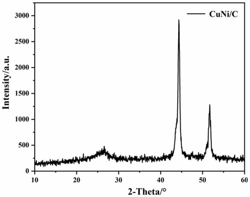
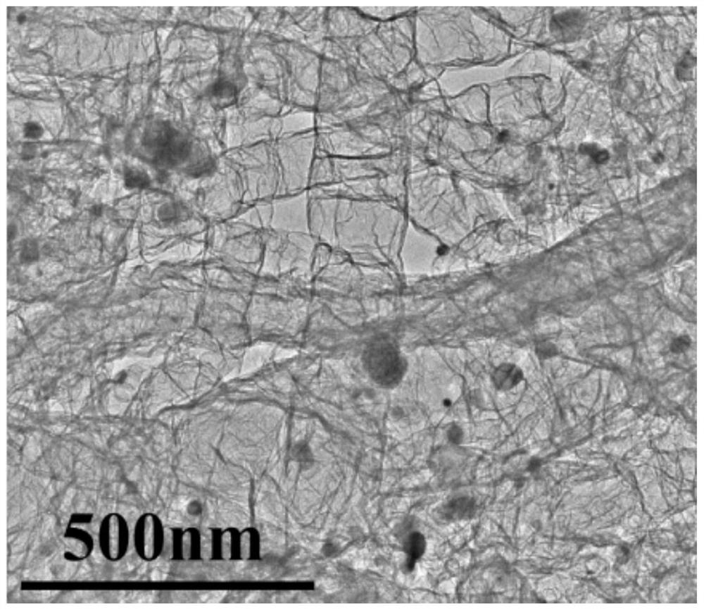
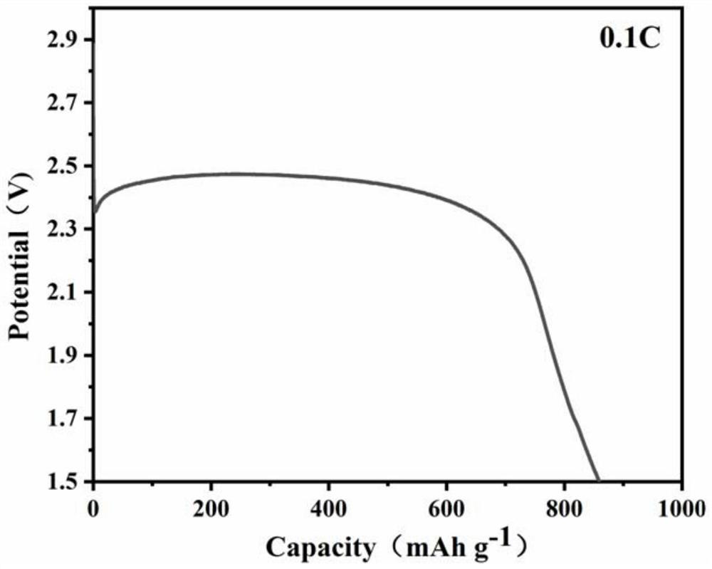
CuNi/C composite catalytic material modified lithium carbon fluoride battery positive plate and preparation method thereof

A lithium carbon fluoride battery and catalytic material technology, which is applied in the direction of primary battery electrodes, battery electrodes, active material electrodes, etc., can solve the problems of hindering the balance of power density and energy density, low conductivity, and low reaction kinetics of batteries , to achieve the effect of improving voltage hysteresis, improving battery performance, and improving conductivity

Pending Publication Date: 2022-01-28
SHAANXI UNIV OF SCI & TECH
View PDF5 Cites 2 Cited by
  • Summary
  • Abstract
  • Description
  • Claims
  • Application Information

AI Technical Summary

Problems solved by technology

[0002] With the rapid development of society, environmental pollution and the shortage of traditional energy sources, carbon fluoride has the highest theoretical specific energy among the cathode materials of lithium primary batteries, and lithium carbon batteries are primary batteries with high energy density, and the practical specific energy can reach 250-700Wh / kg, because the carbon fluoride material is very stable, the capacity retention rate of the lithium carbon fluoride battery is high at high temperature, basically no decay, and the theoretical specific capacity is high. When the carbon ratio x=1, the theoretical specific capacity is as high as 865Ah / g , which is about 3 to 5 times the specific capacity of lithium iron phosphate (170mAh / g) and ternary material (~280mh / g) in the positive electrode material of the secondary battery: but because the electronic conductivity of fluorinated carbon is affected by the degree of fluorination , the introduction of excess F atoms leads to the relatively low conductivity of CFx, as well as the low reaction kinetics of the battery, thus hindering the balance between power density and energy density

Method used


Image

  • CuNi/C composite catalytic material modified lithium carbon fluoride battery positive plate and preparation method thereof
  • CuNi/C composite catalytic material modified lithium carbon fluoride battery positive plate and preparation method thereof
  • CuNi/C composite catalytic material modified lithium carbon fluoride battery positive plate and preparation method thereof

Examples


Embodiment 1

[0031] Step 1: Weigh copper nitrate, nickel sulfate and urea according to the molar ratio of copper, nickel and carbon atoms at 1:8:21 and mix them, add them to the high-speed centrifugal dispersion tank, and put the materials in the high-speed centrifugal dispersion tank at 1500r / min The rotation speed was dispersed for 5 minutes, and then the mixture A was obtained by taking it out;

[0032] Step 2: Put the mixture A in a high-temperature tube furnace, and in a flowing argon atmosphere of 100 sccm, first rapidly raise the temperature from room temperature to 160°C at a rate of 10°C / min, keep it warm for 0.5h, and cool it down naturally After reaching room temperature, take out to obtain product B;

[0033] Step 3: Grind the product B with a mortar for 20 minutes, then put the ground solid powder into a sealed glove box, place it in a crucible under a flowing argon atmosphere of 100 sccm, and in an induction alternating magnetic field environment, the material in the crucible...

Embodiment 2

[0036] Step 1: Weigh copper sulfate, nickel nitrate and melamine according to the molar ratio of copper, nickel and carbon atoms at 1:10:30 and mix them, add them to the high-speed centrifugal dispersion tank, and put the materials in the high-speed centrifugal dispersion tank at 2000r / min Disperse at a rotating speed of 10 minutes, and then take out to obtain the mixture A;

[0037] Step 2: Put the mixture A in a high-temperature tube furnace, and in a flowing nitrogen atmosphere of 100 sccm, first rapidly raise the temperature from room temperature to 200 °C at a rate of 15 °C / min, keep it warm for 1 hour, and cool it naturally to room temperature after the heat preservation is over. After taking out to obtain product B;

[0038] Step 3: Grind product B with a mortar for 25 minutes, then put the ground solid powder into a sealed glove box, place it in a crucible under a flowing nitrogen atmosphere of 100 sccm, and cut the material in the crucible under an induction alternati...

Embodiment 3

[0041] Step 1: Weigh copper sulfate, nickel bromide and glucose according to the molar ratio of copper, nickel and carbon atoms at 1:20:20 and mix them, add them to the high-speed centrifugal dispersion tank, and place the materials in the high-speed centrifugal dispersion tank at 2500r / The rotation speed of min was dispersed for 15 minutes, and then taken out to obtain mixture A;

[0042] Step 2: Put the mixture A in a high-temperature tube furnace, and in a flowing argon atmosphere of 100 sccm, first rapidly raise the temperature from room temperature to 250°C at a rate of 20°C / min, keep it warm for 0.8h, and then cool it down naturally After reaching room temperature, take out to obtain product B;

[0043] Step 3: Grind product B with a mortar for 30 minutes, then put the ground solid powder into a sealed glove box, place it in a crucible under a flowing hydrogen atmosphere of 100 sccm, and cut the material in the crucible under an induction alternating magnetic field envi...


PUM

PropertyMeasurementUnit
diameteraaaaaaaaaa

Abstract

The invention discloses a CuNi / C composite catalytic material modified lithium carbon fluoride battery positive plate, and the positive plate comprises a current collector and an active substance coating coated on the current collector, and the active substance coating comprises the following components in percentage by mass: 70-90% of carbon fluoride powder, 5-20% of catalyst powder and 5-10% of binder; the catalyst is a CuNi / C composite catalytic material. According to the invention, a compound containing a copper source, a nickel source and a carbon source is used for preparing a CuNi / C composite catalytic material serving as a catalyst, and then a current collector is coated with carbon fluoride and the catalyst, so that the required positive plate is obtained. According to the positive plate, the performance of a lithium carbon fluoride battery is improved, the specific energy and storage performance of the battery are improved, the conductivity of a positive electrode material and the rate capability of the battery are improved, and the preparation method has important practical significance.

Description

technical field [0001] The invention belongs to the technical field of batteries, and relates to an electrode sheet and a preparation method thereof, in particular to a CuNi / C composite catalytic material modified lithium carbon fluoride battery positive electrode sheet and a preparation method thereof. Background technique [0002] With the rapid development of society, environmental pollution and the shortage of traditional energy sources, carbon fluoride has the highest theoretical specific energy among the cathode materials of lithium primary batteries, and lithium carbon batteries are primary batteries with high energy density, and the practical specific energy can reach 250-700Wh / kg, because the carbon fluoride material is very stable, the capacity retention rate of the lithium carbon fluoride battery is high at high temperature, basically no decay, and the theoretical specific capacity is high. When the carbon ratio x=1, the theoretical specific capacity is as high as...

Claims


Application Information

Patent Timeline
Patent Type & Authority Applications(China)
IPC IPC(8): H01M4/08H01M4/62H01M4/583H01M4/06H01M6/16
CPCH01M4/08H01M4/06H01M4/5835H01M4/625H01M6/16H01M2004/028
Inventor 李嘉胤钱程郑裕欣黄剑锋曹丽云冯亮亮胡云飞张帅
Owner SHAANXI UNIV OF SCI & TECH
Why Eureka
Try Eureka