N-type 110-micron slice cutting process

A cutting process and thin slice technology, which is applied in the field of N-type 110μm thin slice cutting process, can solve the problems of high brittleness, high hardness, and large slice thickness, achieve good flatness, increase yield, and reduce the generation of fragments.

Inactive Publication Date: 2022-02-01
宜春宇泽新能源有限公司
View PDF0 Cites 1 Cited by
  • Summary
  • Abstract
  • Description
  • Claims
  • Application Information

AI Technical Summary

Problems solved by technology

[0004] The purpose of the present invention is to solve the problem that the current existing cutting process has high hardness and high brittleness of the material, and it is very easy to cause the thickness of the cut sheet to be large due to cracking and edge damage during the cutting process. Type 110μm slice cutting process

Method used


Image

  • N-type 110-micron slice cutting process
  • N-type 110-micron slice cutting process
  • N-type 110-micron slice cutting process

Examples


Embodiment 1

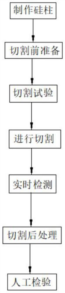
[0029] refer to figure 1 , an N-type 110 μm sheet cutting process, comprising the following steps:

[0030] S1: Making silicon pillars: choose silica sand as the raw material, heat the silica sand to separate carbon monoxide and silicon in the silica sand, and repeat the process until ultra-high-purity electronic-grade silicon is obtained, and high-purity silicon is melted into a liquid and then solidified into a single crystal solid The form makes silicon column, wherein chooses the container that diameter is 32cm when solidifying;

[0031] S2: Preparation before cutting: cut off both ends of the solidified silicon column with a diamond saw, and install a new type of main roller developed by a dedicated domestic high-tech machine installation technician. The error of the measured tension is within 0.1N, and the runout of the main roller is controlled within 10um. Within, install the bonded N-type silicon rod on the machine for cutting;

[0032] S3: Cutting test: The cutting...

Embodiment 2

[0038] refer to figure 1 , an N-type 110 μm sheet cutting process, comprising the following steps:

[0039] S1: Making silicon pillars: choose silica sand as the raw material, heat the silica sand to separate carbon monoxide and silicon in the silica sand, and repeat the process until ultra-high-purity electronic-grade silicon is obtained, and high-purity silicon is melted into a liquid and then solidified into a single crystal solid The form makes silicon column, wherein chooses the container that diameter is 32cm when solidifying;

[0040] S2: Preparation before cutting: cut off both ends of the solidified silicon column with a diamond saw, and install a new type of main roller developed by a dedicated domestic high-tech machine installation technician. The error of the measured tension is within 0.1N, and the runout of the main roller is controlled within 10um. Within, install the bonded N-type silicon rod on the machine for cutting;

[0041] S3: Cutting test: The cutting m...

Embodiment 3

[0047] refer to figure 1 , an N-type 110 μm sheet cutting process, comprising the following steps:

[0048] S1: Making silicon pillars: choose silica sand as the raw material, heat the silica sand to separate carbon monoxide and silicon in the silica sand, and repeat the process until ultra-high-purity electronic-grade silicon is obtained, and high-purity silicon is melted into a liquid and then solidified into a single crystal solid The form makes silicon column, wherein chooses the container that diameter is 32cm when solidifying;

[0049] S2: Preparation before cutting: cut off both ends of the solidified silicon column with a diamond saw, and install a new type of main roller developed by a dedicated domestic high-tech machine installation technician. The error of the measured tension is within 0.1N, and the runout of the main roller is controlled within 10um. Within, install the bonded N-type silicon rod on the machine for cutting;

[0050] S3: Cutting test: The cutting...


PUM

PropertyMeasurementUnit
diameteraaaaaaaaaa

Abstract

The invention relates to the technical field of slice cutting, in particular to an N-type 110-micron slice cutting process, and provides the following scheme aiming at the problem that due to the characteristics of high material hardness and high brittleness in the existing cutting process, the thickness of a cut slice is very large due to breakage and edge breakage in the cutting process. The cutting process comprises the following steps of S1, silicon column manufacturing, S2, preparation before cutting, S3, cutting test and S4, cutting. The invention aims to cut out the N-type silicon wafer with the thickness of 110 mum by improving the existing cutting mode, improve the control method in the subsequent silicon wafer cleaning and inspection process, control the defect ratio within 1%, realize small-batch production, meanwhile, the surface flatness of the cut silicon wafer is good, fragments are reduced, the yield of the silicon wafer is improved, real-time detection is carried out in the silicon wafer cutting process, and the probability of loss caused by abnormal conditions of a machine is reduced.

Description

technical field [0001] The invention relates to the technical field of slice cutting, in particular to an N-type 110 μm slice cutting process. Background technique [0002] In the process of cutting silicon wafers in the solar industry, diamond wire slicers have gradually replaced mortar slicers and become the mainstream of the industry. Compared with the traditional sand wire machine, the diamond wire machine has the absolute advantages of high efficiency, large production capacity, low cost and high yield. Diamond wire slicing machines are gradually localized and widely used in the solar slicing industry. At present, mainstream production enterprises generally use domestic slicers, and gradually get rid of the passive situation of relying on imported machines. An important reason why the diamond wire slicer replaces the traditional mortar slicer is that due to the widespread use of diamond wire cutting, the thinning and thinning of the wire can be promoted. The diameter...

Claims


Application Information

Patent Timeline
Patent Type & Authority Applications(China)
IPC IPC(8): B28D5/04G01N1/28
CPCB28D5/045G01N1/286G01N2001/2873
Inventor 彭云祥刘向荣张霆刘勇姚小威贺斌华龚建国
Owner 宜春宇泽新能源有限公司
Why Eureka
Try Eureka