Biomass negative carbon emission power generation system and working method thereof

A biomass power generation and power generation system technology, applied in the chemical industry, can solve problems such as restricting the large-scale application of direct combustion power generation technology, and achieve the effects of improving biomass utilization, high economic value, and reducing emissions

Pending Publication Date: 2022-02-11
HUANENG CLEAN ENERGY RES INST +1
View PDF0 Cites 0 Cited by
  • Summary
  • Abstract
  • Description
  • Claims
  • Application Information

AI Technical Summary

Problems solved by technology

Among them, direct combustion power generation is a common way to utilize biomass energy, but because the flue gas produced in the process of direct combustion of biomass contains a large number of polluting particles, which restri

Method used


Image

  • Biomass negative carbon emission power generation system and working method thereof

Examples


Embodiment 1

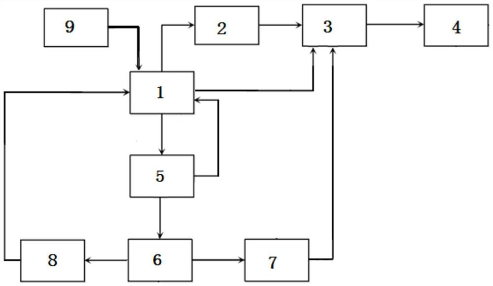
[0040] This embodiment provides a biomass negative carbon emission power generation system, such as figure 1 shown, including:

[0041] Biomass power generation unit 1;

[0042] The flue gas outlet of the biomass power generation unit 1 is connected to the inlet of the flue gas pretreatment unit 2, and the outlet of the flue gas pretreatment unit 2 is connected to the CO of the carbon nanotube unit 3 made of carbon dioxide. 2 Ingress connection;

[0043]The waste water outlet of the biomass power generation unit 1 is connected to the inlet of the water pretreatment unit 5, and the outlet of the water pretreatment unit 5 is connected to the water inlet of the electrolytic hydrogen production unit 6; the hydrogen outlet of the electrolytic hydrogen production unit 6 It is connected with the inlet of the hydrogen gas collection unit 7, and the outlet of the hydrogen gas collection unit 7 is connected with the hydrogen gas inlet of the carbon nanotube made of carbon dioxide unit...

Embodiment 2

[0054] This embodiment provides a working method utilizing the biomass negative carbon emission power generation system of Embodiment 1, including:

[0055] Biomass power generation is performed by the biomass power generation unit 1 to generate electric energy. During the power generation process, the flue gas and waste water generated by the biomass power generation unit 1 are processed and utilized through the following two routes:

[0056] The flue gas produced by the biomass power generation unit 1 enters the flue gas pretreatment unit 2 for treatment and then enters the carbon dioxide carbon nanotube unit 3, and the carbon nanotubes are prepared by electrochemical methods;

[0057] The waste water produced by the biomass power generation unit 1 enters the electrolytic hydrogen production unit 6 after being treated by the water pretreatment unit 5, and the hydrogen gas generated by the electrolytic hydrogen production unit 6 is collected by the hydrogen gas collection unit...


PUM


Abstract

The invention provides a biomass negative carbon emission power generation system and a working method thereof. The biomass negative carbon emission power generation system comprises a biomass power generation unit; a flue gas outlet of the biomass power generation unit is connected with an inlet of a flue gas pretreatment unit, and an outlet of the flue gas pretreatment unit is connected with a CO2 inlet of a carbon-dioxide-prepared carbon nanotube unit; a wastewater outlet of the biomass power generation unit is connected with an inlet of the water pretreatment unit, and an outlet of the water pretreatment unit is connected with a water inlet of an electrolytic hydrogen production unit; and a hydrogen outlet of the electrolytic hydrogen production unit is connected with an inlet of a hydrogen collection unit, and an outlet of the hydrogen collection unit is connected with a hydrogen inlet of the carbon dioxide-prepared carbon nanotube production unit. According to the system, emission of carbon dioxide can be effectively reduced, the biomass utilization rate is increased, the generated product has high economic value, and negative emission of CO2 is achieved.

Description

technical field [0001] The invention relates to the technical field of chemical industry, in particular to a biomass negative carbon emission power generation system and a working method thereof. Background technique [0002] In recent years, with the depletion of fossil energy and the aggravation of environmental pollution, biomass has gradually become one of the promising renewable energy sources. The research, development and application of biomass energy and petroleum substitute products is an effective way to ensure energy supply, reduce dependence on fossil energy, and solve future energy problems. The domestic and foreign biomass energy conversion and utilization technologies are reviewed, mainly including direct combustion technology, biochemical conversion technology (fermentation and anaerobic digestion), thermochemical conversion technology (gasification, pyrolysis), liquefaction technology, compact molding technology, Supercritical fluid conversion technology, e...

Claims


Application Information

Patent Timeline
IPC IPC(8): F01K13/00C01B32/16C25B1/04
CPCF01K13/00C01B32/16C25B1/04Y02E60/36
Inventor 刘蓉王焕君郭东方刘练波郜时旺
Owner HUANENG CLEAN ENERGY RES INST
Why Eureka
Try Eureka