
Automatic winding displacement device for PC steel strand rewinding

A technology of automatic wire arrangement and steel strand, which is applied in the direction of transportation and packaging, sending objects, and conveying filamentous materials, etc. It can solve the problems of winding efficiency discount, equipment idleness, stability impact, etc., so as to improve the degree of compactness , Prevent the coil from loosening, and the effect of preventing the twisted wire from loosening

Pending Publication Date: 2022-02-25
武汉钢铁江北集团金属制品有限公司
View PDF5 Cites 1 Cited by
  • Summary
  • Abstract
  • Description
  • Claims
  • Application Information

AI Technical Summary

Problems solved by technology

[0003] Existing steel strand rewinding or winding equipment, such as a winding device for steel strand production with application number CN201921756647.1, is provided with a fixed plate, a winding roller, a hydraulic rod and a pressure plate, and is driven and fixed by a motor. The rewinding roller on the plate rotates to rewind the steel strand. At the same time, the pressure plate is in contact with the steel strand by adjusting the hydraulic lever, which improves the rewinding effect. However, after the rewinding roller at the coiling station is full, It is necessary to cut off the coiled material after manual shutdown, and then remove the coiled coiled material, and install an empty winding roll to replace it. It takes a lot of time to operate, the winding efficiency is greatly reduced, and the equipment is idle. At the same time, the frequent start and stop of the equipment will also affect the stability of various data when the equipment is running, and increase the failure rate of the equipment.

Method used


Image

  • Automatic winding displacement device for PC steel strand rewinding
  • Automatic winding displacement device for PC steel strand rewinding
  • Automatic winding displacement device for PC steel strand rewinding

Examples


Embodiment Construction

[0031] Below in conjunction with the accompanying drawings of the description of the present invention Figure 1-Figure 8 , clearly and completely describe the specific technical solution of the present invention;

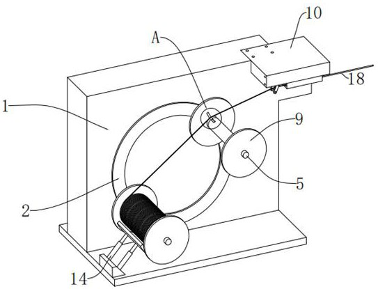
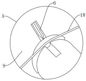
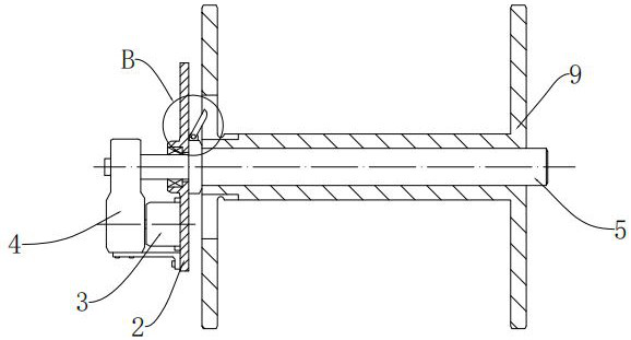
[0032] see Figure 1-Figure 8 , figure 1 It is a schematic diagram of the overall structure of an embodiment of the present invention; figure 2 for the present invention figure 1 The enlarged schematic diagram of the structure at A; image 3 It is a schematic diagram of the winding reel transmission of the present invention; Figure 4 for the present invention image 3 The enlarged schematic diagram of the structure at B; Figure 5 It is a cross-sectional view of the winding reel structure of the present invention; Figure 6 for the present invention Figure 5 The enlarged schematic diagram of the structure at C; Figure 7 It is a schematic diagram of driving the wire rod of the present invention; Figure 8 It is a structural schematic diagram of the pre...


PUM


Abstract

The invention provides an automatic winding displacement device for PC steel strand rewinding; the device comprises a rack and is characterized in that a rotating disc which is driven by a motor to axially rotate along a central point is arranged on the rack, and two winding rotating shafts with symmetrical stations are arranged on the rotating disc; the winding rotating shafts are in transmission connection with a driving motor fixedly installed on the back side of the rotating disc through speed reducers, the winding rotating shafts are sleeved with a winding disc, the winding disc and the winding rotating shafts are in circumferential transmission through a key groove structure, and the winding rotating shafts are provided with cutting-off mechanisms which extend out of a notch in the side surface of the winding disc, cut off the steel strand and fix the end. A feeding mechanism is arranged on one side of the rack and used for feeding materials towards the winding disc side. According to the automatic winding displacement device, due to the arrangement of the double-station alternate winding disc and the automatic cutting mechanism, the steel strand can be automatically cut off without shutdown and efficiently wound, and the automatic winding displacement device has a good development prospect.

Description

technical field [0001] The invention relates to the field of stranded wire winding equipment, in particular to a PC steel stranded wire rewinding automatic wire arranging device. Background technique [0002] PC steel strand is a steel product composed of multiple steel wires twisted. The surface of carbon steel can be added with galvanized layer, zinc-aluminum alloy layer, aluminum-clad layer, copper-plated layer, epoxy resin, etc., and is widely used. Used as reinforcement in prestressed components in the construction industry. The quality of the gripping force between the steel strand and the concrete is an important factor determining the quality of prestressed concrete components, and it is also an important factor in improving the compressive and seismic performance. At the end of the production process of the steel strand, it is often The steel strand is rewinded to eliminate the stress of the coil and the strand is divided into coils, so as to improve the quality of...

Claims


Application Information

Patent Timeline
Patent Type & Authority Applications(China)
IPC IPC(8): B65H54/44B65H35/06
CPCB65H54/44B65H35/06B65H2701/36
Inventor 蔡志超
Owner 武汉钢铁江北集团金属制品有限公司
Learn More