Correction structure and method for eliminating sunspot phenomenon of image sensor

An image sensor and sunspot technology, applied in the field of correction structure of sunspot phenomenon, can solve the problems of large circuit occupation area, increased power consumption, insufficient driving ability, etc., to reduce the occupation area, improve the driving ability and driving ability Enhanced effect

Active Publication Date: 2022-03-01
四川创安微电子有限公司
View PDF12 Cites 0 Cited by
  • Summary
  • Abstract
  • Description
  • Claims
  • Application Information

AI Technical Summary

Problems solved by technology

[0003] As consumers continue to increase the resolution of image sensors, the number of pixel rows and columns in the sensor chip also increases. As a result, the previous sunspot correction structure has insufficient drive capability, and the circuit occupies a large area and consumes a lot of power. problems such as increase

Method used


Image

  • Correction structure and method for eliminating sunspot phenomenon of image sensor
  • Correction structure and method for eliminating sunspot phenomenon of image sensor
  • Correction structure and method for eliminating sunspot phenomenon of image sensor

Examples


Embodiment 1

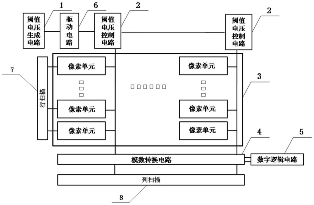
[0048] figure 1 A schematic circuit diagram of a correction structure for eliminating the sunspot phenomenon of an image sensor provided in this embodiment. As shown in the figure, this correction structure includes: a threshold voltage generation circuit 1, a plurality of threshold voltage control circuits 2, a pixel module 3, an analog-to-digital conversion circuit 4, a digital logic circuit 5, a row scan control module 7 and a column scan control module 8 , for driving and selecting the pixel unit output of each row and each column; a plurality of threshold voltage control circuits 2 are connected in parallel on a bus, and the threshold voltage generation circuit 1 is connected to the input end of the bus, and each row A plurality of pixel units are connected on the row scanning control module 7, and a plurality of pixel units of each column are connected on the column scanning control module 8; the pixel module 3 includes multi-row and multi-column pixel units, and the thr...

Embodiment 2

[0061] In combination with the correction structure of Embodiment 1, this embodiment provides a method for eliminating the sunspot phenomenon by using the above correction structure, including:

[0062] Step 1: using the threshold voltage generation circuit to generate a threshold voltage;

[0063] Step 2: using the threshold voltage control circuit to transmit the circuit-generated threshold voltage generated by the threshold voltage to the pixel unit module;

[0064] Step 3: Compensating and correcting the low voltage of the pixel unit through the threshold voltage to obtain a corrected reset voltage of the pixel unit, and ensuring that the reset voltage of the pixel unit is not lower than the threshold voltage;

[0065] Step 4: The pixel module transmits the collected pixel unit reset voltage to the analog-to-digital conversion module, which is obtained after compensating and correcting the pixel unit reset voltage;

[0066] Step 5: using the analog-to-digital conversion c...


PUM


Abstract

The invention discloses a correction structure and method for eliminating a sunspot phenomenon of an image sensor. The correction structure comprises a threshold voltage generation circuit, a plurality of threshold voltage control circuits, a pixel module, an analog-to-digital conversion circuit and a digital logic circuit, the plurality of threshold voltage control circuits are connected in parallel on a bus, and the threshold voltage generation circuit is connected with the input end of the bus; the pixel module comprises a plurality of columns of pixel units, and the threshold voltage control circuits are connected with the single columns of pixel units in a one-to-one correspondence manner; and the pixel module, the analog-to-digital conversion circuit and the digital logic circuit are connected in sequence. According to the method, the sunspots can be logically judged, and the sunspot phenomenon can be effectively eliminated.

Description

technical field [0001] The invention relates to the technical field of image sensors, in particular to a correction structure and method for eliminating the sunspot phenomenon of image sensors. Background technique [0002] Complementary Metal Oxide Semiconductor (CMOS) type image sensors have occupied the mainstream market of image sensors in recent years. When taking pictures of objects with strong light such as the sun, the CMOS image sensor has a very strong light energy in the central part of the luminescence, so that the large number of electrons obtained by the photodiode after photoelectric conversion is very easy to overflow. Due to the existence of the switch tube Leak in the transmission circuit of the pixel module, a large amount of electrons overflow from the pixel module to the signal sampling capacitor, which causes the reset voltage of the pixel module obtained by sampling to be too low (close to the output signal voltage after photoelectric conversion of the...

Claims


Application Information

Patent Timeline
Patent Type & Authority Applications(China)
IPC IPC(8): H04N5/361H04N5/374H01L27/146
CPCH01L27/14601H04N25/63H04N25/76
Inventor 不公告发明人
Owner 四川创安微电子有限公司
Why Eureka
Try Eureka