Gas-based shaft furnace direct reduction method for hydrocarbon-rich gas and reduction system thereof

A gas-based shaft furnace and shaft furnace technology, which is applied to shaft furnaces, furnaces, furnace types, etc., can solve the problems of large investment, high outlet temperature of transition section, and complicated installation, and achieve the effect of reducing investment and reducing overall investment.

Pending Publication Date: 2022-03-15
李伟
View PDF2 Cites 2 Cited by
  • Summary
  • Abstract
  • Description
  • Claims
  • Application Information

AI Technical Summary

Problems solved by technology

[0002] At present, the gas-based shaft furnace direct reduction process has the following problems: (1) The raw material gas mainly comes from hydrocarbon-rich gas (such as natural gas, coke oven gas) and shaft furnace top gas. need to remove CO 2 , so the top gas system is installed to remove CO 2 decarburization unit
This type of tube heating furnace has the following problems: a. Since the reformer tubes are heated externally, the diameter of the reformer tubes is limited, resulting in a small volume of a single reformer tube and a large number of reformer tubes
This results in huge equipment for the heating system in the radiation chamber and complicated installation; b. The temperature at the outlet of the transition section is as high as 1200°C, which means that the temperature of the reformer tube is higher than 1200°C. Such reformer tubes and burners are very expensive. The reformer equipment usually needs hundreds of reformer tubes, so the investment is too large; c. The catalyst is expensive, the use is large, and it needs to be replaced regularly, so the production and operation costs are high; d. The exhaust gas and the use of flue gas waste heat The equipment in the transition section and the convection section is huge and the structure is complex, which again increases the investment cost

Method used


Image

  • Gas-based shaft furnace direct reduction method for hydrocarbon-rich gas and reduction system thereof
  • Gas-based shaft furnace direct reduction method for hydrocarbon-rich gas and reduction system thereof
  • Gas-based shaft furnace direct reduction method for hydrocarbon-rich gas and reduction system thereof

Examples


Embodiment 1

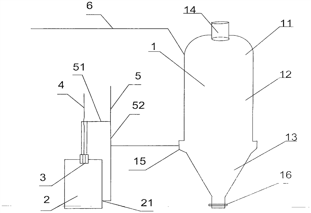
[0048] see figure 1 . Natural gas is used as the hydrocarbon-rich gas. Iron oxides with a particle size of 8-16 mm are fed into the gas-based shaft furnace 1 from a furnace top charging device 14 . The hydrocarbon-rich gas main pipe 5 leads to two branch pipes, and the oxygen 4 and the hydrocarbon-rich gas in the first branch pipe 51 pass into the burner 3 in the reformer 2, and the volume ratio of the oxygen 4 to the hydrocarbon-rich gas is about 70%. The pressure in the oxidation reformer 2 is 0.5Mpa, oxygen 4 and hydrocarbon-rich gas are anoxic and combusted in the reformer to generate H 2 and CO, at reformer 2 outlet line 21, the gas reaches 1350°C. Inject the unheated hydrocarbon-rich gas through the second branch pipeline 52 of the hydrocarbon-rich gas into the outlet pipeline 21 of the reformer 2 whose gas temperature reaches 1350° C. to form a mixed gas. The hydrocarbon-rich gas first branch pipe 51 and the second branch pipe 52 The internal flow ratio is about 2-3...

Embodiment 2

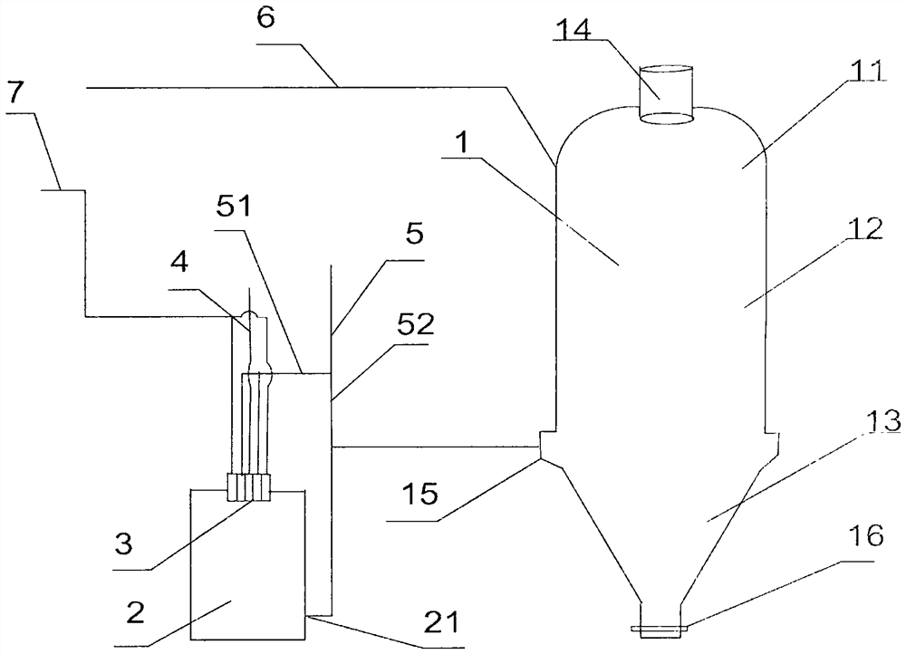
[0050] see figure 2 . The hydrocarbon-rich gas is coke oven gas. Iron oxides with a particle size of 8-16 mm are fed into the gas-based shaft furnace 1 from a furnace top charging device 14 . The hydrocarbon-rich gas main pipe 5 leads to two branch pipes, the oxygen 4 and the hydrocarbon-rich gas in the first branch pipe 51 pass into the burner 3 in the reformer 2, and the water vapor passes through the steam main pipe 7 into the outer ring channel of the burner 3 , the volume ratio of oxygen 4 to hydrocarbon-rich gas is about 28%, and the pressure in partial oxidation reformer 2 is 0.7Mpa. Oxygen 4 and hydrocarbon-rich gas burn anoxic in the reformer to generate H 2 and CO, at reformer 2 outlet line 21, the gas reaches 1200°C. Inject the unheated hydrocarbon-rich gas through the second branch pipeline 52 of the hydrocarbon-rich gas into the outlet pipeline 21 of the reformer 2 whose gas temperature reaches 1200°C to form a mixed gas. The hydrocarbon-rich gas first branch ...

Embodiment 3

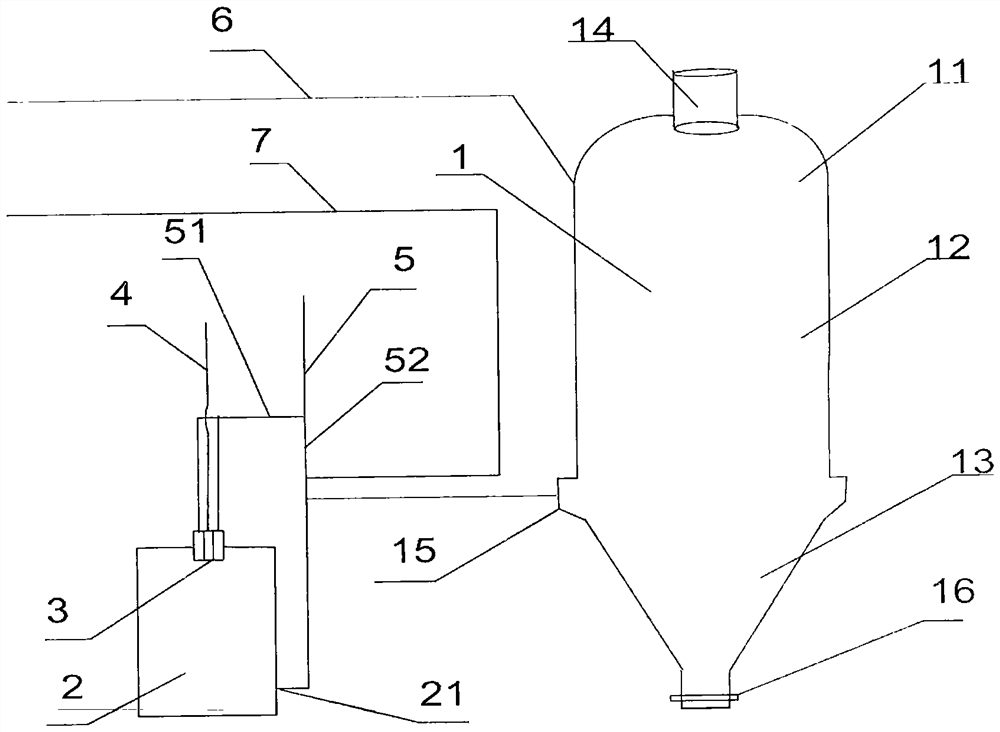
[0052] see image 3 . The hydrocarbon-rich gas is coalbed methane. Iron oxides with a particle size of 8-16 mm are fed into the gas-based shaft furnace 1 from a furnace top charging device 14 . The hydrocarbon-rich gas main pipe 5 leads to two branch pipes. The oxygen 4 and the hydrocarbon-rich gas in the first branch pipe 51 are passed into the burner 3 in the reformer 2. The volume ratio of the oxygen 4 to the hydrocarbon-rich gas is about 65%. The pressure in the oxidation reformer 2 is 0.1Mpa, oxygen 4-5 and hydrocarbon-rich gas are anoxic and combusted in the reformer to generate H 2 and CO, at reformer 2 outlet line 21, the gas reaches 1200°C. The steam in the steam main pipe 7 is passed into the second branch pipeline 52 of the rich hydrocarbon gas, and then the mixed gas of the steam and the rich hydrocarbon gas is injected into the reformer 2 outlet pipeline 21 to form a new mixed gas, and the rich hydrocarbon gas is The flow ratio in the first branch pipe 51 and ...


PUM


Abstract

The invention discloses a hydrocarbon-rich gas gas-based shaft furnace direct reduction method and a reduction system thereof, and belongs to the field of direct reduction. Reducing gas is hydrocarbon-rich gas, the hydrocarbon-rich gas and an oxidizing agent are heated to 1100-1350 DEG C in a heating device, then unheated hydrocarbon-rich gas is injected to form mixed gas, then the mixed gas is sprayed into the gas-based shaft furnace, a lining of the heating device is a refractory material, and the oxidizing agent is one or a mixture of more than two of O2, H2O and CO2. The reduction system comprises a gas-based shaft furnace and a gas heating device, a partial oxidation converter is adopted as the gas heating device, hydrocarbon-rich gas is divided into two pipelines, one pipeline is communicated with an inlet of the partial oxidation converter heating device, and the other pipeline is connected with an outlet pipeline of the partial oxidation converter heating device in parallel and then is communicated with the partial oxidation converter heating device. And then communicating with a reducing section tuyere of the strange furnace body. The invention has the advantages of low overall investment, high utilization rate of feed gas and high conversion rate of hydrocarbon-rich gas, and solves the problem of efficient utilization of coal gases with different properties in iron and steel combined enterprises.

Description

technical field [0001] The invention belongs to the field of direct reduction, and in particular relates to a method for direct reduction of a gas-based shaft furnace rich in hydrocarbons and a reduction system thereof. Background technique [0002] At present, the gas-based shaft furnace direct reduction process has the following problems: (1) The raw material gas mainly comes from hydrocarbon-rich gas (such as natural gas, coke oven gas) and shaft furnace top gas. need to remove CO 2 , so the top gas system is installed to remove CO 2 decarburization device. For example, the patent application number 201710676084.4, the patent titled a gas-based shaft furnace reducing gas preparation system and method proposes that the gas-based shaft furnace reducing gas preparation system includes a gas-based shaft furnace top gas scrubber, a top gas degasser Carbon plant, coke oven gas purification unit, coke oven gas desulfurization unit, reformer, heat recovery unit, synthesis gas ...

Claims


Application Information

Patent Timeline
Patent Type & Authority Applications(China)
IPC IPC(8): C21B13/02
CPCC21B13/02C21B13/0073
Inventor 张春雷张力元
Owner 李伟
Why Eureka
Try Eureka