
Method for manufacturing chemical mechanical polishing dresser

A technology of chemical machinery and dresser, which is applied in the direction of manufacturing tools, grinding machine parts, grinding/polishing equipment, etc., can solve the problem of inconsistency in the size, shape, orientation and exposed height of diamond abrasives, difficulty in processing three-dimensional microstructures, The problem of weak diamond holding power can be achieved to improve the trimming quality and efficiency, the effect of processing heat is small, and the scanning speed is fast.

Active Publication Date: 2022-03-25
ZHENGZHOU RES INST FOR ABRASIVES & GRINDING CO LTD
View PDF11 Cites 1 Cited by
  • Summary
  • Abstract
  • Description
  • Claims
  • Application Information

AI Technical Summary

Problems solved by technology

[0005] In view of the deficiencies in the above-mentioned background technology, the present invention proposes a method for manufacturing a chemical mechanical polishing trimmer, which uses laser precision machining technology to process the pyramid microstructure array on the substrate, which can effectively solve the problem of difficult processing and processing of the three-dimensional microstructure on the surface of the ceramic substrate. The problem of low efficiency and serious wear of the grinding wheel can realize precision machining of microstructures with different structures, sizes, and spacings, and solve the problems of non-uniform size, shape, orientation, and exposed height of diamond abrasives in traditional dressers, as well as weak diamond holding power. Ensure the trimming quality and efficiency of the polishing pad and improve the CMP polishing quality of the wafer

Method used


Image

  • Method for manufacturing chemical mechanical polishing dresser
  • Method for manufacturing chemical mechanical polishing dresser
  • Method for manufacturing chemical mechanical polishing dresser

Examples


Embodiment 1

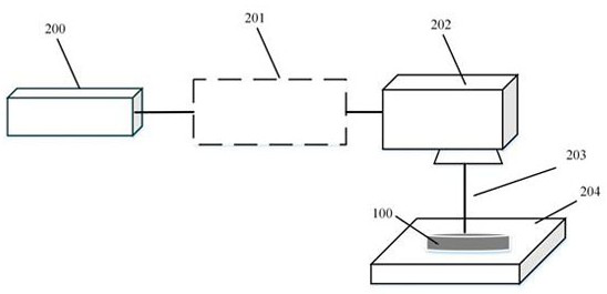
[0033] A method for manufacturing a chemical mechanical polishing trimmer, the processing system platform includes an ultraviolet picosecond laser 200, a laser optical path 201, a three-dimensional scanning galvanometer 202, a three-axis numerical control platform 204, and a laser beam 203 is output from the ultraviolet picosecond laser 200, Through the laser optical path 201, it is injected into the three-dimensional scanning vibrating mirror 202, and the three-dimensional scanning vibrating mirror 202 controls the laser to quickly scan and process the ceramic substrate on the three-axis numerical control platform 204 in the three-dimensional direction to obtain a ceramic substrate with a pyramid structure on the surface, and then A diamond film with a uniform thickness is deposited on the surface of the ceramic substrate by hot wire chemical vapor deposition, that is, a chemical mechanical polishing trimmer is manufactured.

Embodiment 2

[0035] A method for manufacturing a chemical mechanical polishing trimmer, the specific steps are as follows:

[0036] (1) Build a processing system platform: The built laser processing system platform includes an ultraviolet picosecond laser, a laser optical path, a three-dimensional scanning galvanometer, and a three-axis numerical control platform.

[0037] (2) Clamp and fix the cleaned ceramic substrate on the three-axis CNC platform, and move the upper surface of the ceramic substrate to the plane position of the laser focus, waiting for processing.

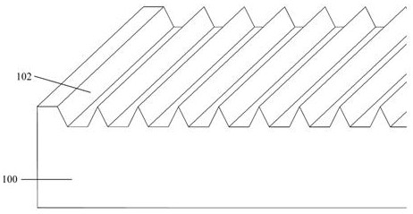
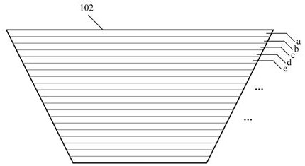
[0038] (3) The laser is controlled by the 3D scanning galvanometer to scan the ceramic substrate in step (2) along the first direction, and a number of inverted trapezoidal grooves are processed, and the tops of two adjacent inverted trapezoidal grooves meet to form apexes .

[0039] (4) After the groove processing in the first direction of the substrate in step (3), the laser is controlled by the three-dimensional scanning...

Embodiment 3

[0042] A method for manufacturing a chemical mechanical polishing trimmer, the specific steps are as follows:

[0043](1) The laser processing system platform built includes an ultraviolet picosecond laser 200, a laser optical path 201, a three-dimensional scanning galvanometer 202, and a three-axis numerical control platform 204. The three-dimensional scanning galvanometer 202 can control the laser light 203 to perform rapid scanning in the three-dimensional direction according to the designed processing path.

[0044] (2) Clamping and fixing the cleaned ceramic substrate 100 on the three-axis numerical control platform 204, and moving the upper surface of the ceramic substrate 100 to the focus position of the laser 203 of the three-dimensional scanning galvanometer, waiting for processing.

[0045] (3) The laser 203 is controlled by the three-dimensional scanning galvanometer 202 to scan the ceramic substrate 100 in step (2) along the first direction, and several inverted tr...


PUM

PropertyMeasurementUnit
Thicknessaaaaaaaaaa

Abstract

The invention discloses a method for manufacturing a chemical mechanical polishing finisher, and belongs to the technical field of laser finish machining. A platform of the machining system comprises a purple picosecond laser, a laser light path, a three-dimensional scanning galvanometer and a three-axis numerical control platform, a laser beam is output from the purple picosecond laser and enters the three-dimensional scanning galvanometer through the laser light path, the three-dimensional scanning galvanometer controls laser to conduct rapid scanning machining on a ceramic matrix on the three-axis numerical control platform in the three-dimensional direction, and the three-dimensional scanning galvanometer conducts three-dimensional machining on the ceramic matrix on the three-axis numerical control platform. And then a diamond film with the uniform thickness is deposited on the surface of the base body through hot filament chemical vapor deposition, and the chemical mechanical polishing trimmer is manufactured. According to the manufacturing method, precision machining of microstructures of different structures, sizes and intervals is achieved, the problems that the size and shape of a diamond abrasive of a traditional trimmer are weak, and the diamond holding force is weak are solved, then the trimming quality and efficiency of a polishing pad are guaranteed, and the polishing quality of chemical mechanical polishing of wafers is improved.

Description

technical field [0001] The invention belongs to the technical field of laser precision machining, and in particular relates to a method for manufacturing a chemical mechanical polishing trimmer. Background technique [0002] The ultra-planar processing of wafers is the basis for realizing the precision manufacturing of semiconductor chips, and the chemical mechanical polishing (CMP) process is an indispensable technology for realizing ultra-planar processing of wafers. The CMP process relies on the combination of chemical action and mechanical action to polish the surface of the wafer through the polishing pad and polishing liquid. However, during the polishing process, the polishing pad will age due to elastic fatigue, which will reduce the surface roughness. The debris and impurities will block the pores of the polishing pad, glaze the surface of the polishing pad, and lose the polishing function. It is necessary to use a chemical mechanical polishing conditioner to dress ...

Claims


Application Information

Patent Timeline
IPC IPC(8): B24D18/00B24B53/017B23K26/352B23K26/082B23K26/70B23K103/00
CPCB24D18/009B24D18/00B24B53/017B23K26/352B23K26/082B23K26/702B23K2103/52
Inventor 方旭阳李彬王帅包华
Owner ZHENGZHOU RES INST FOR ABRASIVES & GRINDING CO LTD
Learn More