
Reflow soldering machining tool and machining method for motor server power device

A technology of power devices and servers, which is applied in the direction of assembling printed circuits, electrical components, and printed circuits with electrical components. It can solve the problems of low thermal conductivity, multi-space, and increased current carrying capacity of printed circuit boards to speed up processing. , The processing procedure is simple, and the effect of avoiding the bad effect of the workpiece

Pending Publication Date: 2022-03-25
SUZHOU GST INFOMATION TECH CO LTD
View PDF0 Cites 0 Cited by
  • Summary
  • Abstract
  • Description
  • Claims
  • Application Information

AI Technical Summary

Problems solved by technology

However, in the scenario of large current carrying, due to the low heat conduction efficiency of the base material of the traditional printed circuit board, it is not conducive to the overall heat dissipation, and it is difficult for the printed circuit board to further increase the current carrying capacity by increasing the copper thickness. To achieve the purpose of increasing the current carrying capacity, however, additional soldering of copper bars will take up more space; and in the traditional reflow soldering process, the position of components is prone to shift because they are not fixed and limited, resulting in mis-soldering , missing soldering and other undesirable phenomena; in addition, for those power devices that do not contain printed circuit board substrates, it is difficult to process them through the reflow soldering process

Method used


Image

  • Reflow soldering machining tool and machining method for motor server power device
  • Reflow soldering machining tool and machining method for motor server power device
  • Reflow soldering machining tool and machining method for motor server power device

Examples


Embodiment Construction

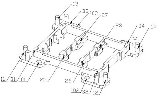
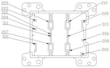
[0038]The technical solution of the present invention will be described in detail below in conjunction with the embodiments and accompanying drawings. The present invention discloses a reflow soldering processing tool for a motor servo power device and a corresponding processing method. The specific technical solution is as follows.

[0039] A reflow soldering processing tool for a motor-servo power device is characterized in that the motor-servo power device includes an insulated gate transistor module, a functional module, and a copper substrate 8 at the bottom from top to bottom.

[0040] The functional module includes a phase current output board module, a grid control board module, and a DC input board module, and the phase current output board module, the grid control board module, and the DC input board module are set On the same level, the insulated gate transistor module includes 6 identical insulated gate transistors arranged on the same level, the insulated gate tran...


PUM


Abstract

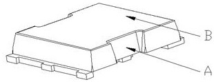
The invention provides a reflow soldering machining tool and machining method for a motor server power device. The machining tool comprises a hollowed-out machining frame matched with a marginal gate type transistor module. The lower surface of the machining frame horizontally extends outwards in the diagonal direction to form a positioning plate module with the thickness smaller than that of the machining frame, and a positioning column module used for fixing a copper substrate is vertically and upwards arranged on the upper surface of the positioning plate module in a protruding mode. The upper surface of the processing frame is provided with a first supporting surface module used for fixing the copper substrate in the vertical direction, and the processing frame is internally provided with a second positioning column module which is vertically arranged and a second supporting surface module which is horizontally arranged and is used for fixing the edge gate type transistor module. The method has the advantages that good heat conductivity of the stacked structure in the reflow soldering process is guaranteed, the heat dissipation performance of the whole structure is enhanced, and by the adoption of the machining method, the reject ratio of products is reduced, and the machining efficiency is improved.

Description

technical field [0001] The invention relates to a reflow soldering processing tool and a processing method, in particular to a reflow soldering processing tool and a processing method of a motor servo power device, and belongs to the technical field of servo drive systems. Background technique [0002] With the rapid development of the electronic processing industry, the development of SMT technology is also becoming more and more perfect. With the emergence of various SMT components and SMT devices, the reflow soldering process technology and equipment as part of the SMT technology have also been developed accordingly. Almost all The domain of electronic products has been applied. Reflow soldering technology is also used in the assembly of hybrid integrated circuit boards. Most of the components assembled and welded are capacitors, inductors, mount transistors and diodes. There is a heating circuit inside the reflow soldering equipment. Its working principle is to heat the...

Claims


Application Information

Patent Timeline
IPC IPC(8): H05K3/34
CPCH05K3/34H05K3/3494
Inventor 陈盈宇
Owner SUZHOU GST INFOMATION TECH CO LTD
Learn More