Integrated experimental device for researching soil remediation activation method
An activation method and soil remediation technology, applied to chemical instruments and methods, feeding devices, preparation of test samples, etc., can solve the problems of limited scope of application and low available value, and achieve reasonable structure setting and save operation Difficulty and operation time, improve various new effects
- Summary
- Abstract
- Description
- Claims
- Application Information
AI Technical Summary
Problems solved by technology
Method used
Image
Examples
Embodiment 1
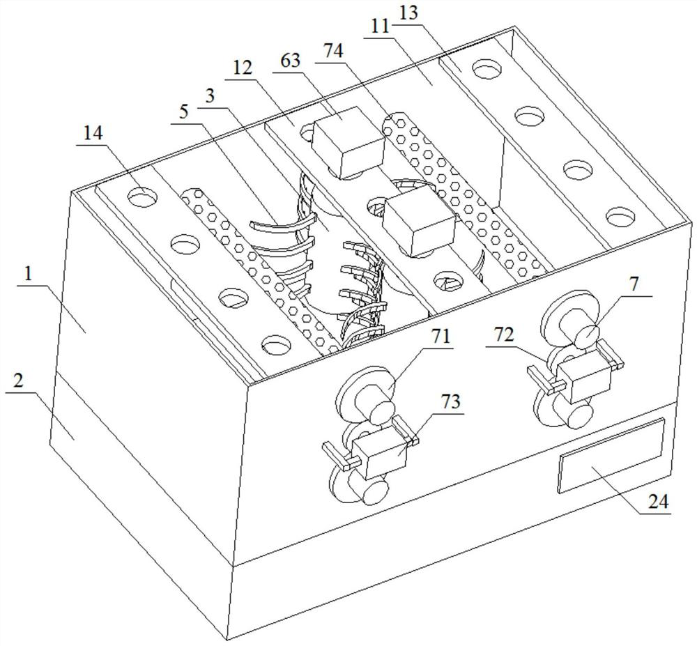
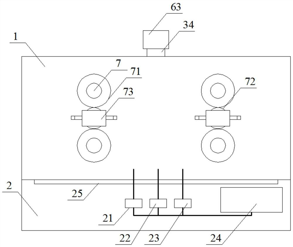
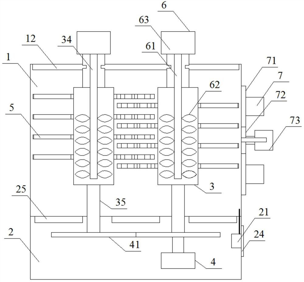
[0033] Such as figure 1 , 5 As shown, an integrated experimental device for the study of soil remediation and activation methods, including a main body 1 and a base 2 located below the main body 1, an opening 11 is arranged above the main body 1, the base 2 is hollow, and the middle part of the top surface of the main body 1 is set. Cathode electrode placement plate 12 is arranged, and anode electrode placement plate 13 is arranged on both sides of main body 1 top surface, and cathode electrode placement plate 12 and anode electrode placement plate 13 surface all have 5 groups of placement holes 14, each on cathode electrode placement plate 12 Between the two groups of placement holes 14, there is a set of dosing barrels 3 respectively. There are two groups of dosing barrels 3 and they are arranged in parallel. 33;
[0034] Such as figure 2 As shown, the inside of the base 2 is attached to the bottom of the main body 1 and is provided with a pH monitor 21 for monitoring th...
Embodiment 2
[0040] This embodiment is basically the same as Embodiment 1, the difference lies in that the internal structure of the dosing barrel 3 is set differently.
[0041] Specifically, such as Figure 5-8 As shown, the inside of the thickened inner wall 32 on both sides of the groove 322 is respectively provided with a group of water pipes 36, which are used to communicate with the drug mixing chamber 33 and the groove 322. The water pipe 36 communicates with the groove 322 and one end is the water outlet 362. When the sliding block 325 is not connected with the slot 54, the sliding block 325 seals and blocks the position of the water outlet 362. When the sliding block 325 is connected with the slot 54, the water outlet is opened. 362, the inside of the sliding block 325 is provided with a through hole 326 that runs through the bottom of the sliding block 325 and the inclined surface, and the position of the through hole 326 corresponding to the inside of the slot 54 is provided wit...
Embodiment 3
[0043] This embodiment is basically the same as Embodiment 1, except that the number of stirring rod groups is different.
[0044] The dosing barrel 3 is rotatably connected with the cathode electrode placement plate 12 through the limit block 34 provided on its top, and the rotating rod 35 provided at the bottom of the dosing barrel 3 penetrates the bottom of the main body 1 and connects with the upper surface of the rotating gear 41 inside the base 2 The center is connected, and the lower surface of one group of rotating gears 41 is provided with a rotating motor 4 for controlling its rotation. The rotating motor 4 is a commercially available three-phase reduction motor. The outer wall 31 of barrel 3 is provided with 3 sets of stirring rod groups, and the stirring rod groups of each dosing barrel 3 are arranged at equal intervals from top to bottom, and the stirring rod groups of two dosing barrels 3 are arranged alternately.
PUM
 Abstract
Description
Claims
Application Information
 - R&D
- Intellectual Property
- Life Sciences
- Materials
- Tech Scout
- Unparalleled Data Quality
- Higher Quality Content
- 60% Fewer Hallucinations
Browse by: Latest US Patents, China's latest patents, Technical Efficacy Thesaurus, Application Domain, Technology Topic, Popular Technical Reports.
© 2025 PatSnap. All rights reserved.Legal|Privacy policy|Modern Slavery Act Transparency Statement|Sitemap|About US| Contact US: help@patsnap.com


