
Electric drive system and automobile

A technology on the other side, motor cooling, applied in the direction of electromechanical devices, electrical components, electric components, etc., can solve the problems of large axial and radial dimensions of electric drives, unfavorable layout of electric drive systems, and rise in oil temperature of reducers, etc. Achieve the effect of reducing resistance, improving flexibility and reducing overall height

Pending Publication Date: 2022-04-12
CHINA FIRST AUTOMOBILE
View PDF7 Cites 3 Cited by
  • Summary
  • Abstract
  • Description
  • Claims
  • Application Information

AI Technical Summary

Problems solved by technology

Although most motors, electronic controls, and reducers currently use three-in-one or multi-in-one drive systems, motors, controllers, and reducers are generally independent assemblies that are protected and installed with independent casings, and motors, controls The cooling system of the reducer and reducer is designed independently. The heat dissipation of the motor and the controller is usually connected through a soft connection or a split connection. The disadvantage is that the assembly process is complicated. The connection of water pipes not only increases the number of parts but also increases the cost, and the heat dissipation water channel of the motor and the heat dissipation water channel of the motor integrated controller need to be connected with a sealed structure, which has the risk of leakage. At the same time, the simple physical integration of the motor, electric control, and reducer will lead to The large axial and radial dimensions of the electric drive are not conducive to the layout of the electric drive system, and there are also serious challenges to the miniaturization of the electric drive system
In addition, since the reducer is close to the end of the motor winding, it cannot effectively dissipate heat nearby, and the baking of the motor will cause the oil temperature of the reducer to rise. Once it exceeds the suitable oil temperature working range of the reducer, the working condition of the reducer will deteriorate. The efficiency is reduced, and how to effectively dissipate heat from the reducer has become an urgent problem to be solved

Method used


Image

  • Electric drive system and automobile
  • Electric drive system and automobile
  • Electric drive system and automobile

Examples


Embodiment Construction

[0045] In order to make the technical problems solved by the present invention, the technical solutions adopted and the technical effects achieved clearer, the technical solutions of the embodiments of the present invention will be further described in detail below in conjunction with the accompanying drawings. Obviously, the described embodiments are only the technical solutions of the present invention. Some, but not all, embodiments. Based on the embodiments of the present invention, all other embodiments obtained by those skilled in the art without making creative efforts belong to the protection scope of the present invention.

[0046] In the description of the present invention, unless otherwise clearly specified and limited, the terms "connected", "connected" and "fixed" should be understood in a broad sense, for example, it can be a fixed connection, a detachable connection, or an integrated ; It can be a mechanical connection or an electrical connection; it can be a d...


PUM


Abstract

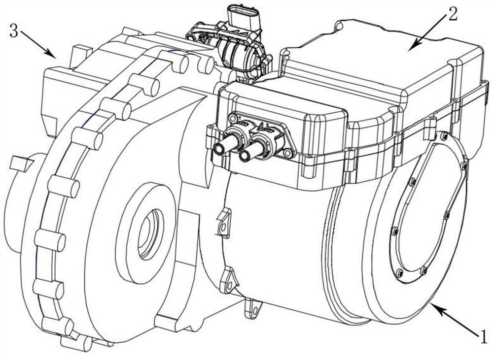
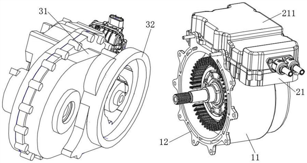
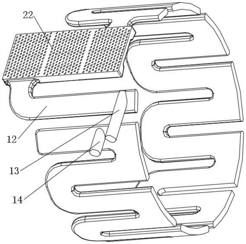
The invention relates to the technical field of new energy automobiles, and particularly discloses an electric drive system and an automobile. According to the inverter cooling water channel of the electric drive system, the inverter assembly and one part of the motor assembly are cooled in parallel, and then the other part of the motor assembly is cooled in series, so that the cooling water channel of the electric drive system is wholly shortened, and the flowing resistance of cooling liquid is reduced. The motor assembly and the inverter assembly are integrated in the radial direction, the motor assembly and the inverter assembly share a cooling water channel, the overall height of the electric drive system in the radial direction is reduced, the motor assembly and the speed reducer assembly are integrated in the axial direction, and the axial length of the electric drive system is reduced; the motor assembly and the inverter assembly share the cooling water channel, so that the cooling water channel of the electric drive system is shortened, the use of fastening parts, sealing parts and the like for connecting the cooling water channel of the inverter and the cooling water channel of the motor is reduced, and the risk of leakage of cooling liquid is reduced; in addition, the cooling water channel of the electric drive system can cool the speed reducer assembly at the same time.

Description

technical field [0001] The invention relates to the technical field of new energy vehicles, in particular to an electric drive system and a vehicle. Background technique [0002] With the gradual development and maturity of new energy vehicle products, the space inside the car is becoming more and more compact. As an important power system of new energy vehicles, the motor control system has higher and higher requirements for light weight, miniaturization, integration and cost reduction. . Although most of the motors, electronic controls, and reducers currently use a three-in-one or multi-in-one drive system, the motor, controller, and reducer are generally independent assemblies that are protected and installed with independent housings, and the motor, control The cooling system of the gearbox and reducer is designed independently. The heat dissipation of the motor and the controller is usually connected through a soft connection or a split connection. The disadvantage is ...

Claims


Application Information

Patent Timeline
Patent Type & Authority Applications(China)
IPC IPC(8): H02K5/20H02K9/19H02K11/30H02K7/116H02K11/27H05K7/20
Inventor 刘金锋赵慧超钱志超苍衍郭璐璐宋鹏飞文彦东
Owner CHINA FIRST AUTOMOBILE
Learn More