Near-zero-emission multi-energy complementary combined power generation system and control method

A combined power generation and subsystem technology, applied in the electric power industry, can solve the problems of large fluctuations in wind power generation and photovoltaic power generation grid connection, and achieve the effects of reduced power consumption, simple process, and large tolerance

Active Publication Date: 2022-04-15
SOUTH CHINA UNIV OF TECH
View PDF3 Cites 0 Cited by
  • Summary
  • Abstract
  • Description
  • Claims
  • Application Information

AI Technical Summary

Problems solved by technology

[0005] The present invention combines the working principle of existing wind power generation, photovoltaic power generation and gas-steam combined cycle and the configuration of each component, and introduces gas-steam combined cycle to balance the fluctuation of wind power and photovoltaic power generation, and organically combines and sets the two power generation forms The corresponding work and control logic can effectively solve the problem of large fluctuations in wind power generation and photovoltaic power generation grid connection, and the system achieves near-zero emissions while ensuring the overall stable output of electric energy

Method used


Image

  • Near-zero-emission multi-energy complementary combined power generation system and control method
  • Near-zero-emission multi-energy complementary combined power generation system and control method
  • Near-zero-emission multi-energy complementary combined power generation system and control method

Examples


Embodiment

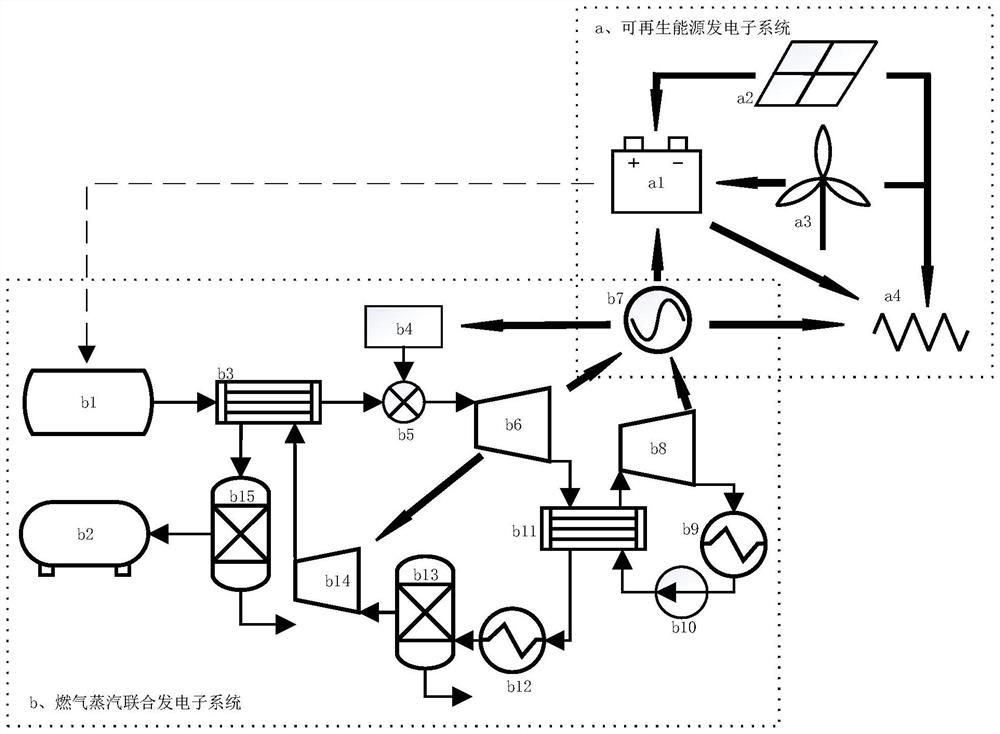
[0044] Such as figure 1 As shown, a near-zero carbon emission multi-energy complementary combined power generation system includes renewable energy power generation sub-system a and gas-steam co-generation sub-system b.

[0045] The renewable energy generation sub-system includes an energy storage device a1, a photovoltaic power generation device a2, a wind power generation device a3 and a power grid a4;

[0046]The gas-steam combined power generation sub-system b includes LNG storage device b1, CO 2 Storage device b2, first heat exchanger b3, air separation oxygen generator b4, burner b5, gas turbine b6, generator b7, steam turbine b8, first air cooler b9, water pump b10, second heat exchanger b11, The second air cooler b12, the first gas-liquid separator b13, the compressor b14, and the second gas-liquid separator b15.

[0047] The specific connection method is as follows:

[0048] The power output terminals of the photovoltaic power generation device a2 are respectively ...

Embodiment 2

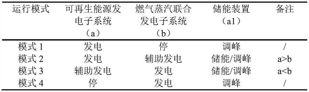
[0064] A control method for a near-zero emission multi-energy complementary combined power generation system, comprising

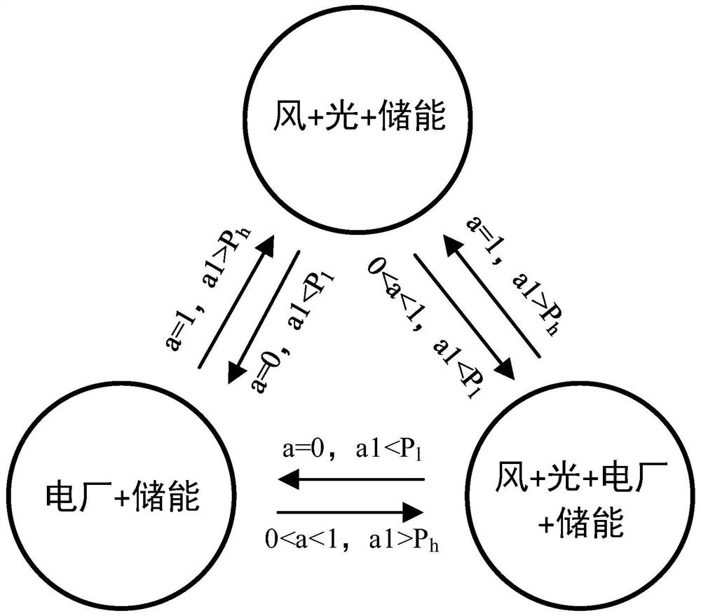
[0065] In the renewable energy generation sub-system a, due to changes in external conditions such as sunlight or wind, the output power of the photovoltaic power generation device a2 and the wind power generation device a3 will fluctuate. a4 The way of power transmission ensures the stability of the overall power supply. When the electric energy stored in the energy storage device a1 rises to a high set value or drops to a low set value, a signal is sent to the LNG storage device b1.

[0066] In the gas-steam combined power generation sub-system b, the LNG storage device b1 receives the signal from the energy storage device a1 to increase or decrease the output of LNG, and the increase or decrease of the output of LNG makes the high-temperature and high-pressure flue gas at the outlet of the burner b5 (generated by CO 2 , water vapor and a small amount o...


PUM


Abstract

The invention discloses a near-zero-emission multi-energy complementary combined power generation system and a control method. The near-zero-emission multi-energy complementary combined power generation system comprises a renewable energy power generation subsystem and a gas-steam combined power generation subsystem. When the generated power of the renewable energy power generation subsystem is larger than the required power of the power grid, the redundant electric energy is transmitted to the energy storage device, and when the total transmission power of the renewable energy power generation subsystem cannot meet the requirement of the power grid due to the change of external conditions such as illumination and wind speed, the energy storage device is started. If yes, the gas-steam combined power generation subsystem transmits electric energy to the power grid to keep the total output power of the system stable. According to the system and the method, the gas-steam combined power generation is introduced to supplement the wind-solar combined power generation, and the gas-steam combined power generation subsystem is dynamically controlled according to the stored electric quantity of the energy storage device, so that the problem that the power grid is greatly disturbed due to non-uniform output of the wind-solar power generation can be effectively solved; overall electricity, heat and cold multi-combined supply is achieved, and meanwhile near-zero carbon emission of the system is achieved.

Description

technical field [0001] The invention relates to the technical field of electric power industry, in particular to a nearly zero-emission multi-energy complementary combined power generation system and a control method. Background technique [0002] The energy crisis is one of the most concerned focuses of all countries in the world today. Since the industrial revolution, the energy required for human industrialization has been provided by traditional fossil energy such as coal and oil. However, this resource is not only limited, but also produces serious emissions. people's ecological environment. The shortage of energy and the deterioration of the environment have prompted human beings to develop renewable and clean energy. Among them, solar energy and wind energy have great potential for development. These two energy sources are inexhaustible, clean and safe. Through years of active development of solar energy and wind energy, as of 2020, the cumulative installed capacity ...

Claims


Application Information

Patent Timeline
Patent Type & Authority Applications(China)
IPC IPC(8): H02J3/38H02J3/46H02J3/28
CPCY02E10/56Y02E10/76Y02E70/30
Inventor 廖艳芬韩逸骁马晓茜
Owner SOUTH CHINA UNIV OF TECH
Why Eureka
Try Eureka