Check patentability & draft patents in minutes with Patsnap Eureka AI!

Optical phase-locked loop device

A phase-locked loop, optical technology, applied in optics, nonlinear optics, lasers, etc., can solve the problems of restricting the promotion and use of optical phase-locked loops, residual phase noise fluctuations of coherent lasers, and additional phase shifts in the loop, and improve the Lock Band Range, Large Tuning Range, Capture Band Large Effects

Pending Publication Date: 2022-04-19
BEIJING CHANGCHENG INST OF METROLOGY & MEASUREMENT AVIATION IND CORP OF CHINA
View PDF0 Cites 3 Cited by
  • Summary
  • Abstract
  • Description
  • Claims
  • Application Information

AI Technical Summary

Problems solved by technology

[0005] The existing optical phase-locked loop device only uses a mixer to adjust the frequency difference of the coherent laser by directly adjusting the reference frequency. When the reference frequency changes, the performance of the optical phase-locked loop changes accordingly, resulting in fluctuations in the residual phase noise of the coherent laser. , and will produce an unpredictable additional phase shift of the loop, which will introduce additional systematic errors to the experimental results
In addition, existing optical phase-locked loop devices often use commercial frequency-locked controllers to achieve laser locking, which has problems such as high price and large size, and needs to be equipped with additional high-voltage drivers to control piezoelectric ceramics, which limits the promotion of optical phase-locked loops and use

Method used


Image

  • Optical phase-locked loop device
  • Optical phase-locked loop device
  • Optical phase-locked loop device

Examples


Embodiment 1

[0044]In this embodiment, after forming an optical phase-locked loop closed-loop locking, the frequency difference between the two lasers corresponds to the distance between the ground state hyperfine splitting structures of alkali metal rubidium 87 atoms of 6.834 GHz as an example.

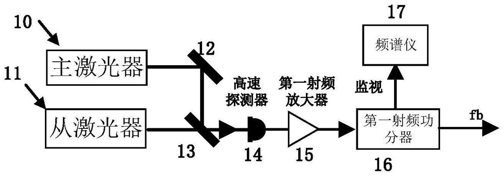
[0045] Such as figure 1 As shown, an optical phase-locked loop device disclosed in this embodiment includes: a laser beat frequency module 1, a microwave frequency mixing module 2, a frequency discrimination module 3 and a loop filter module 4;

[0046] The laser beat frequency module 1 obtains the laser beat frequency signal to be locked, and the microwave frequency mixing module 2 down-converts the laser beat frequency signal to a local oscillator signal in the radio frequency band, and the local oscillator signal is compared with the reference signal in the frequency discrimination and phase discrimination module 3 to obtain The phase detection signal, the phase detection signal is processed b...


PUM


Abstract

The invention relates to an optical phase-locked loop device, and belongs to the field of coherent laser preparation methods in atomic physics and quantum optics. The optical phase-locked loop device comprises a laser beat frequency module, a microwave frequency mixing module, a frequency and phase detection module and a loop filtering module, the laser beat frequency module obtains a beat frequency signal to be locked, the microwave frequency mixing module performs down-conversion on the beat frequency signal to obtain a local oscillator signal, the local oscillator signal is compared with a reference signal in the frequency and phase detection module to obtain a phase detection signal, the phase detection signal is processed by the loop filtering module to obtain a feedback signal to control the laser, and closed-loop locking of the optical phase-locked loop is formed. According to the invention, the double-balanced mixer and the up-conversion mixer are combined for mixing, when the laser frequency difference is adjusted, a local oscillator signal is kept unchanged, so that the optical phase-locked loop always works at the optimal performance position, the size of a locking band is improved, no extra loop phase shift is generated, and the optical phase-locked loop is suitable for preparation of high-performance coherent laser; according to the invention, the loop filter completely replaces an expensive and heavy commercial frequency locking controller.

Description

technical field [0001] The invention relates to an optical phase-locked loop device, which belongs to the field of coherent laser preparation methods in the field of atomic physics and quantum optics. Background technique [0002] Phase-coherent lasers have extremely important applications in the frontier research fields of light-matter interactions, including: coherent population-captured atomic clocks, precision spectroscopy, atomic interferometers, etc. In the above applications, it is very necessary to generate two laser beams with a frequency difference between tens of MHz and several GHz and a highly coherent phase. For example, in the cold atom interference gravimeter of alkali metal rubidium 87 atoms, two coherent laser Locked near 6.834GHz, the residual phase noise and additional phase shift of the coherent laser will have an important impact on the accuracy of the gravitational acceleration measurement. [0003] At present, there are many methods or technologies f...

Claims


Application Information

Patent Timeline
IPC IPC(8): G02F1/35H01S3/10H01S3/13
CPCG02F1/353H01S3/10053H01S3/1307
Inventor 白金海鲍莹莹胡栋王宇
Owner BEIJING CHANGCHENG INST OF METROLOGY & MEASUREMENT AVIATION IND CORP OF CHINA
Features
  • R&D
  • Intellectual Property
  • Life Sciences
  • Materials
  • Tech Scout
  • Unparalleled Data Quality
  • Higher Quality Content
  • 60% Fewer Hallucinations
Learn More