
Burner for producing inorganic spheroidized particles, device for producing inorganic spheroidized particles, and method for producing inorganic spheroidized particles

A burner and inorganic technology, applied in the direction of combustion methods, chemical instruments and methods, burners, etc., can solve the problems that cannot fully ensure the residence time of the burner flame (heating time, unable to give heat, etc.)

Pending Publication Date: 2022-05-06
NIPPON SANSO CORP
View PDF3 Cites 0 Cited by
  • Summary
  • Abstract
  • Description
  • Claims
  • Application Information

AI Technical Summary

Problems solved by technology

On the contrary, if the injection speed of the carrier gas is increased, the residence time (heating time) in the burner flame cannot be sufficiently ensured, and sufficient heat cannot be given to melt particles with a large particle size.
[0015] In the conventional diffusion burners disclosed in the above-mentioned Patent Documents 1 to 3, the raw material powder is supplied to the burner flame together with the carrier gas from the vicinity of the center of the burner, and it is difficult to efficiently melt the following inorganic powder. And spheroidized, the inorganic powder has a large particle size distribution including particles (fine particles) with a particle size of about several μm to particles (coarse particles) with a particle size of tens of μm to hundreds of μm

Method used


Image

  • Burner for producing inorganic spheroidized particles, device for producing inorganic spheroidized particles, and method for producing inorganic spheroidized particles
  • Burner for producing inorganic spheroidized particles, device for producing inorganic spheroidized particles, and method for producing inorganic spheroidized particles
  • Burner for producing inorganic spheroidized particles, device for producing inorganic spheroidized particles, and method for producing inorganic spheroidized particles

Examples


Embodiment Construction

[0078]

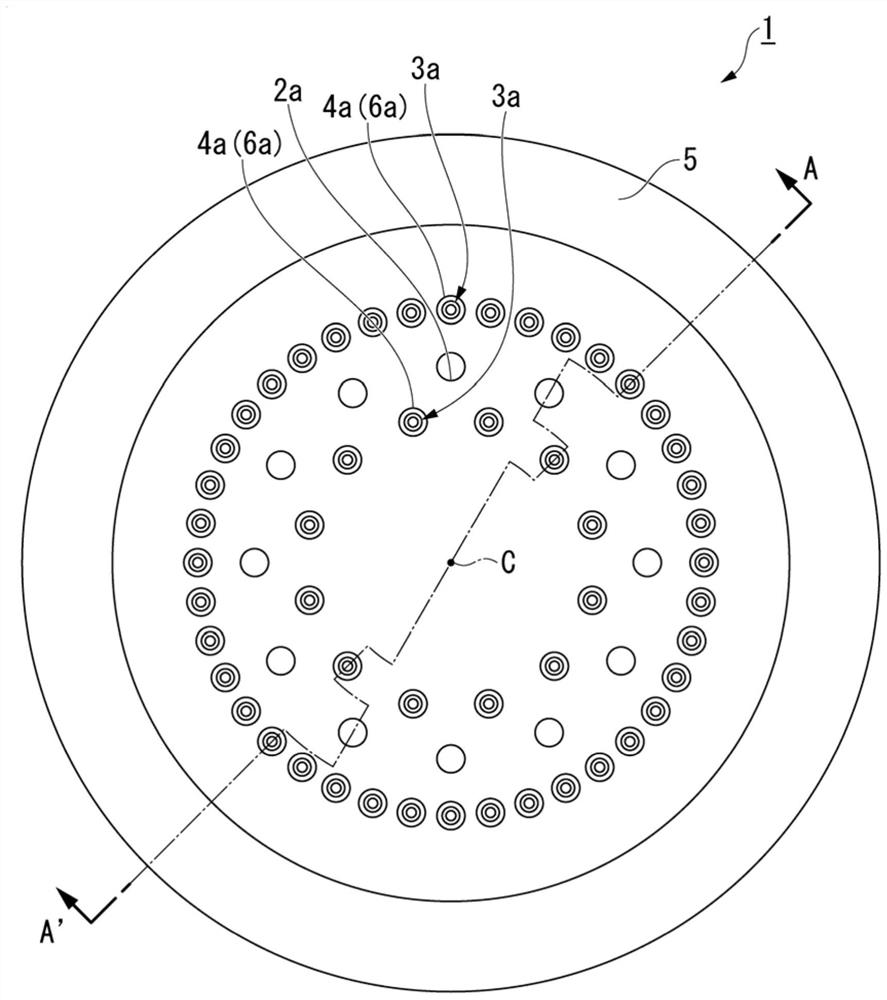
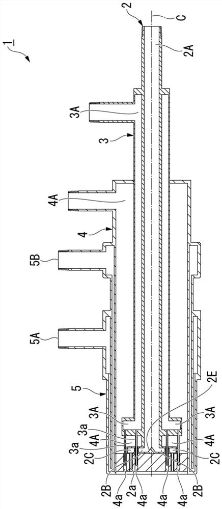
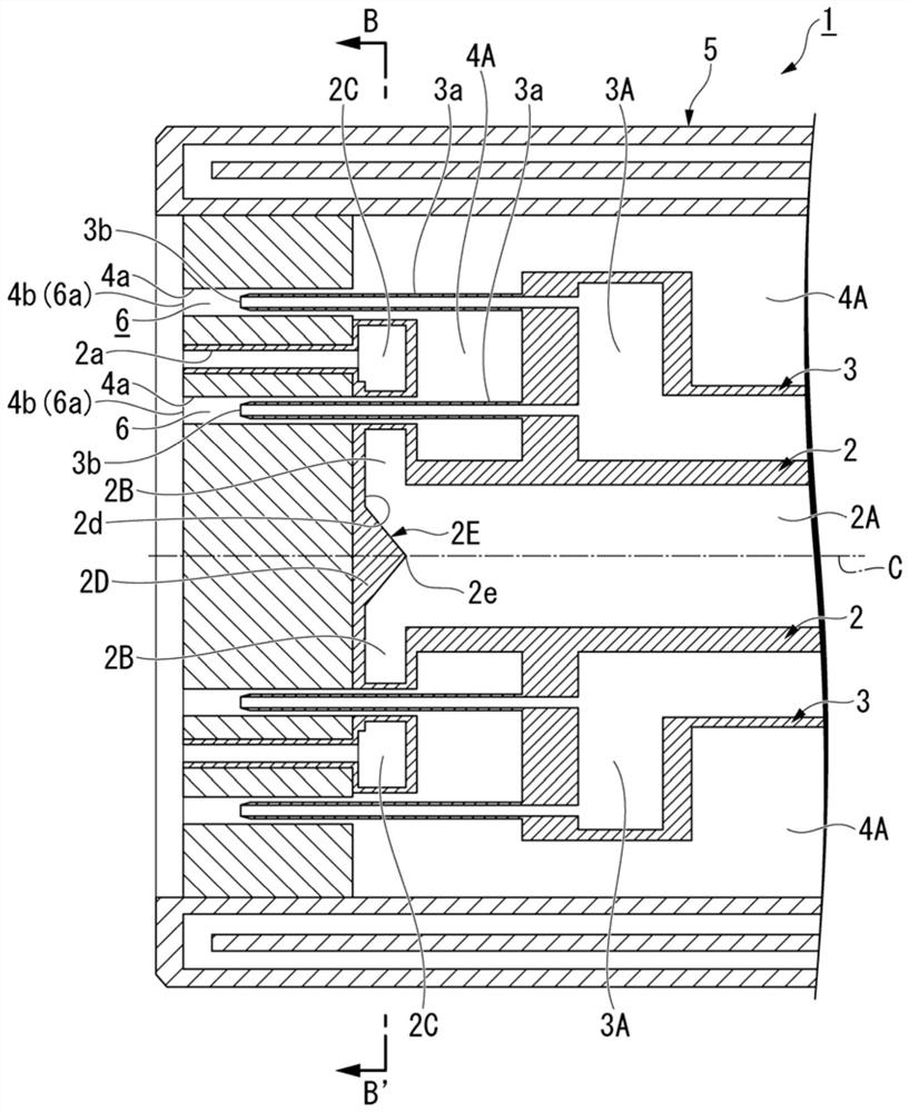
[0079] Hereinafter, a burner for producing spheroidized inorganic particles as a first embodiment to which the present invention is applied will be described in detail together with an apparatus for producing spheroidized inorganic particles and a production method using the same, using the drawings. In addition, in the drawings used in the following description, characteristic parts may be shown enlarged for the sake of easy understanding of features and for convenience, and the dimensional ratio of each component may not necessarily be the same as the actual one.

[0080] (Burner for manufacturing inorganic spheroidized particles)

[0081] First, the structure of the burner for producing spheroidized inorganic particles according to the first embodiment will be described. Figure 1 to Figure 4 A burner for producing spheroidized inorganic particles (hereinafter, may be simply referred to as a "burner") as a first embodiment to which the present invention is applie...


PUM


Abstract

The purpose of the present invention is to provide a burner for producing inorganic spheroidized particles, which is capable of efficiently melting an inorganic powder having a large particle size distribution and making the inorganic powder into a spherical shape. Provided is a burner (1) for producing inorganic spheroidized particles, comprising: a raw material powder supply path for supplying an inorganic powder as a raw material powder; a first fuel gas supply path (3A) for supplying a first fuel gas; and a first combustion-supporting gas supply path (4A) that supplies a first combustion-supporting gas. The raw material powder supply path has: a first supply path (2A) that extends in the axial direction of the burner (1); a first collision wall (2D) located at the tip of the first supply path (2A); a plurality of second supply paths (2B) branching from the tip of the first supply path (2A) and extending in the radial direction from the center of the combustor (1); one or more dispersion chambers (2C) located at the tip of the second supply path (2B) and having a wider space than the second supply path; and one or more raw material powder discharge holes (2a) communicating with the dispersion chamber (2C).

Description

technical field [0001] The present invention relates to a burner for producing spheroidized inorganic particles, an apparatus for producing spheroidized inorganic particles, and a method for producing spheroidized inorganic particles. Background technique [0002] Conventionally, methods for producing inorganic spheroidized particles (hereinafter, sometimes simply referred to as "spheroidized particles") by passing an inorganic powder raw material through a flame are known (Patent Documents 1 to 3). [0003] For example, in the inorganic spheroidized particle manufacturing apparatus disclosed in Patent Document 2, as Figure 12 As shown, the raw material powder is supplied from the raw material supply device (feeder) A, and is conveyed to the burner B together with the carrier gas supplied from the carrier gas supply device A'. Oxygen from the oxygen supply facility C and fuel gas (liquefied petroleum gas: LPG) from the LPG supply facility D are supplied to the burner B. Th...

Claims


Application Information

Patent Timeline
Patent Type & Authority Applications(China)
IPC IPC(8): F23D14/02F23D14/22F23D14/48F23D14/62B01J2/00
CPCF23D14/02F23D14/48F23D14/62F23D14/22B01J2/00F23D2203/007C01B33/18C01B13/145B05B7/205C01F5/02C01F7/021C01G49/06C01P2004/32F23D14/70F27B1/005F27B1/06F27B1/08F27D2017/009
Inventor 山本康之萩原义之山口雅志
Owner NIPPON SANSO CORP
Learn More