Active dynamic membrane VOCs waste gas treatment system and process

A waste gas treatment and dynamic membrane technology, applied in gas treatment, membrane technology, air quality improvement, etc., can solve problems such as reduced operating efficiency, air pollution, and exhaust gas environmental pollution, to improve operating efficiency, reduce operating costs, and improve removal efficiency effect

Pending Publication Date: 2022-05-31
重庆众源盛特环保设备制造有限公司
View PDF8 Cites 0 Cited by
  • Summary
  • Abstract
  • Description
  • Claims
  • Application Information

AI Technical Summary

Problems solved by technology

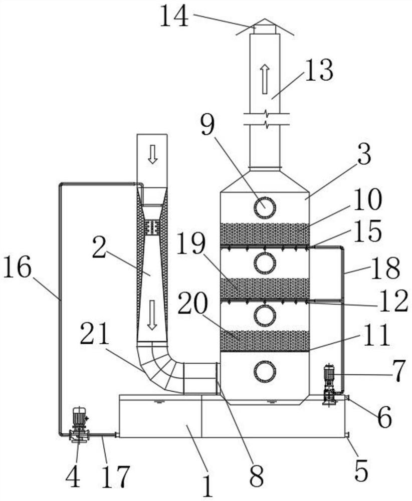
With the help of the kinetic energy of the exhaust gas, the aqueous solution with the active agent is promoted to form tiny droplets, that is, an active dynamic membrane is formed to promote gas-liquid mass transfer, thereby improving the removal efficiency of VOC. However, the tiny droplets produced by the above-mentioned active dynamic membrane generator It is easy to be taken away with the air flow, on the one hand, it will lead to the loss of the active agent, resulting in an increase in processing costs; on the other hand, the tiny droplets with the active agent are discharged into the air, causing air pollution
In industrial production, industrial desiccants or fixed fillers are usually used for adsorption treatment of tiny droplets, but the above adsorption treatment will also lead to the loss of active agents
On the other hand, it is impossible to improve the removal efficiency of VOCs in the exhaust gas, which leads to a decrease in the operating efficiency of the system. Second, it is impossible to treat the exhaust gas generated in the active dynamic membrane VOCs exhaust gas treatment system, resulting in pollution of the exhaust gas to the environment and harm to the human body. Harmful, and can not achieve recycling, which increases the operating cost of waste gas treatment

Method used


Image

  • Active dynamic membrane VOCs waste gas treatment system and process
  • Active dynamic membrane VOCs waste gas treatment system and process
  • Active dynamic membrane VOCs waste gas treatment system and process

Examples


Embodiment Construction

[0030] The technical solutions in the embodiments of the present invention will be clearly and completely described below with reference to the accompanying drawings in the embodiments of the present invention. Obviously, the described embodiments are only a part of the embodiments of the present invention, rather than all the embodiments. Based on the embodiments of the present invention, all other embodiments obtained by those of ordinary skill in the art without creative efforts shall fall within the protection scope of the present invention.

[0031]In the description of the present invention, it should be noted that the terms "center", "upper", "lower", "left", "right", "vertical", "horizontal", "inner", "outer", etc. The indicated orientation or positional relationship is based on the orientation or positional relationship shown in the accompanying drawings, which is only for the convenience of describing the present invention and simplifying the description, rather than ...


PUM


Abstract

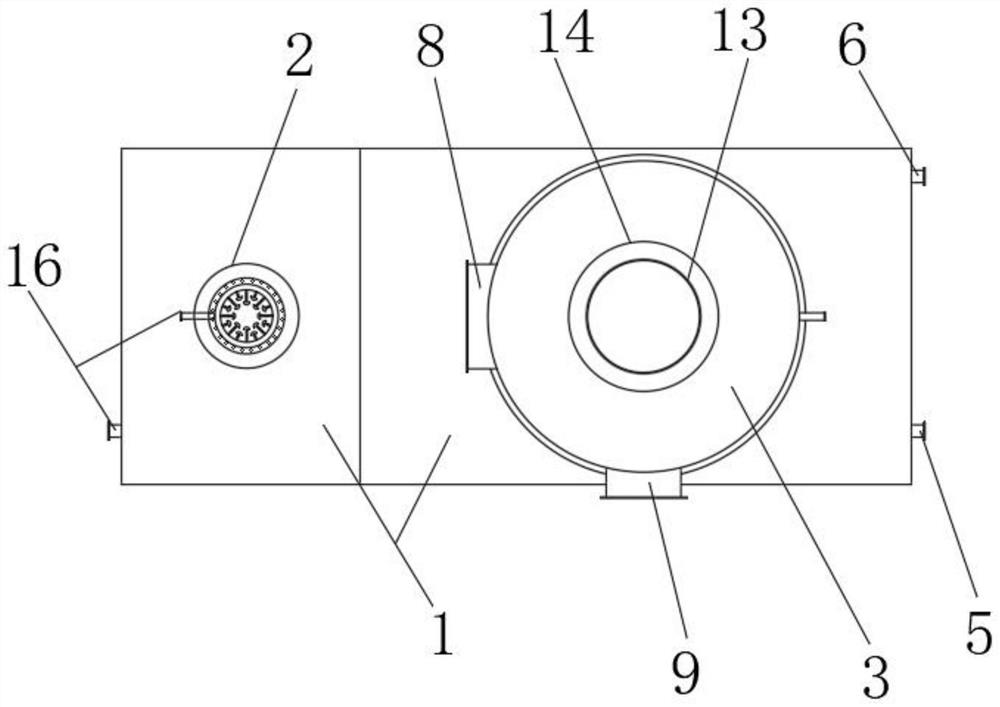
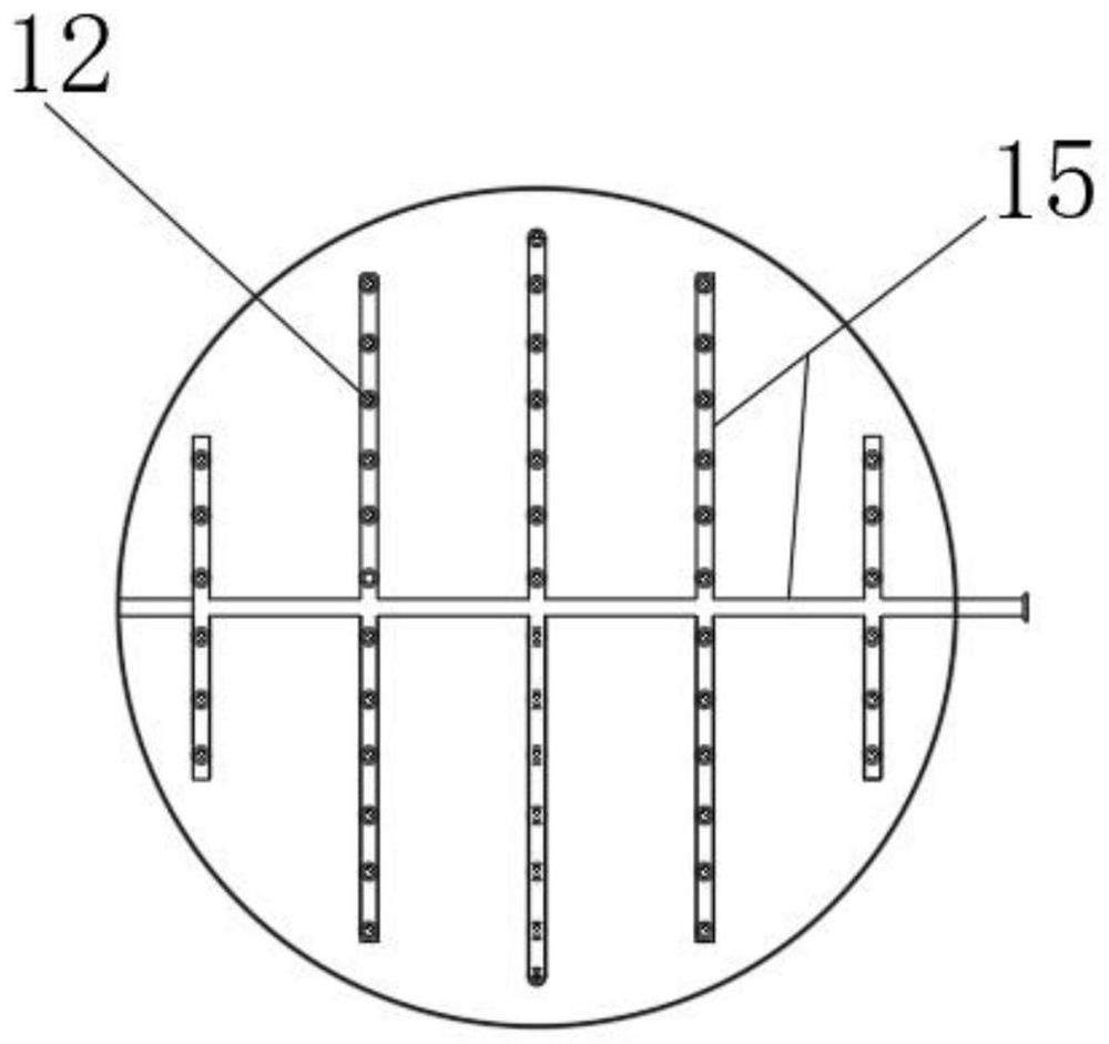
The invention relates to the technical field of VOCs waste gas treatment, and discloses an active dynamic membrane VOCs waste gas treatment system which comprises an active circulating liquid transfer tank, an active dynamic membrane generator and an active agent recoverer. The right end of the connecting pipe is fixedly connected into a connecting opening in the bottom end of the left side of an active agent recoverer, the top of the active agent recoverer is fixedly connected to the bottom of a purifier discharging barrel, and a first filler layer, a second filler layer and a third filler layer are sequentially arranged in the active agent recoverer from top to bottom. According to the invention, the circulating liquid spraying device formed by the active circulating liquid distributor and the active circulating liquid pipeline adopts a mode that the first filler layer, the second filler layer, the third filler layer and the circulating liquid spraying device are arranged at intervals, so that on one hand, the absorption of tiny water drops and the effective recovery of an active agent are realized; on the other hand, the removal efficiency of the VOCs in the waste gas is improved.

Description

technical field [0001] The invention relates to the technical field of VOCs waste gas treatment, in particular to an active dynamic membrane VOCs waste gas treatment system. Background technique [0002] Volatile organic compounds (VOCs) usually refer to various organic compounds with a boiling point below 260 °C at room temperature, mainly composed of alkanes, aromatic hydrocarbons, olefins, halogenated hydrocarbons, esters, aldehydes, ketones and other types. It is composed of organic compounds. There are usually a large number of VOCs in the production workshops of paint production, automobile painting, organic synthesis, etc. Most of the volatile organic compounds (VOCs) are harmful substances to the human body, and some are also carcinogenic. Substances such as cyclic aromatic hydrocarbons and nitrosamines, some of which are carcinogenic, such as halogenated hydrocarbons, aromatic amines, etc., volatile organic compounds (VOCs) are one of the main factors of ambient air...

Claims


Application Information

Patent Timeline
IPC IPC(8): B01D53/79B01D53/44B01D53/18
CPCB01D53/79B01D53/44B01D53/18B01D53/1487B01D2257/708Y02A50/20
Inventor 陈旭王小平陈刚牟坚刘剡
Owner 重庆众源盛特环保设备制造有限公司
Why Eureka
Try Eureka