
Resistance-free relaxation oscillator based on capacitor plate exchange

A relaxation oscillator and capacitor plate technology, which is applied in the field of non-resistor relaxation oscillators, can solve the problems of short positive pulse time, large layout area, and large current consumption, and achieve layout area realization, large layout area, and improved power supply efficiency Effect

Pending Publication Date: 2022-06-07
ANYKA (GUANGZHOU) MICROELECTRONICS TECH CO LTD
View PDF0 Cites 0 Cited by
  • Summary
  • Abstract
  • Description
  • Claims
  • Application Information

AI Technical Summary

Problems solved by technology

The first is the delay T r There is a contradiction with the discharge operation of the switch SW. If in order to obtain an accurate clock frequency, it is necessary to reduce the delay T of the comparator as much as possible r , but the extremely low delay T r It will cause the positive pulse time to be too short, and the short positive pulse time will cause the switch SW to fail to switch V C Bleed to V SS1 Afterwards, the comparator COMP feeds back a new closing signal, thereby shortening the width of the next clock cycle
In order to solve the problem of insufficient discharge, a delay chain is usually added behind the comparator, but the delay of the inverter delay chain is just a nonlinear function of time, thus deteriorating the frequency-temperature stability of the oscillator , that is, larger loop delays result in lower frequency-temperature stability and larger layout area at low output frequencies
The second is that it is difficult for the oscillator to achieve a very low resonance frequency, because T1=T r +T C =T r +RC, in order to reduce the frequency, you need to increase R or C or increase R and C synchronously. You can also use a multi-stage frequency divider in the subsequent stage to obtain a low-frequency clock, but for IoT and other systems, if you use a frequency divider to obtain low-frequency clock, the original high-frequency oscillator and frequency divider will consume a large amount of current, resulting in a sharp increase in power consumption; if the RC value is increased instead of the frequency divider, the space required for passive components will be reduced Consumes a huge layout area and increases the cost of producing chips

Method used


Image

  • Resistance-free relaxation oscillator based on capacitor plate exchange
  • Resistance-free relaxation oscillator based on capacitor plate exchange
  • Resistance-free relaxation oscillator based on capacitor plate exchange

Examples


Embodiment Construction

[0024] The following will clearly and completely describe the technical solutions in the embodiments of the present invention with reference to the accompanying drawings in the embodiments of the present invention. Obviously, the described embodiments are only some, not all, embodiments of the present invention. Based on the embodiments of the present invention, all other embodiments obtained by persons of ordinary skill in the art without creative efforts fall within the protection scope of the present invention.

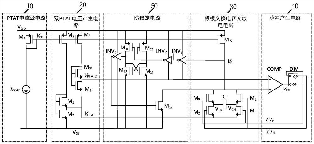
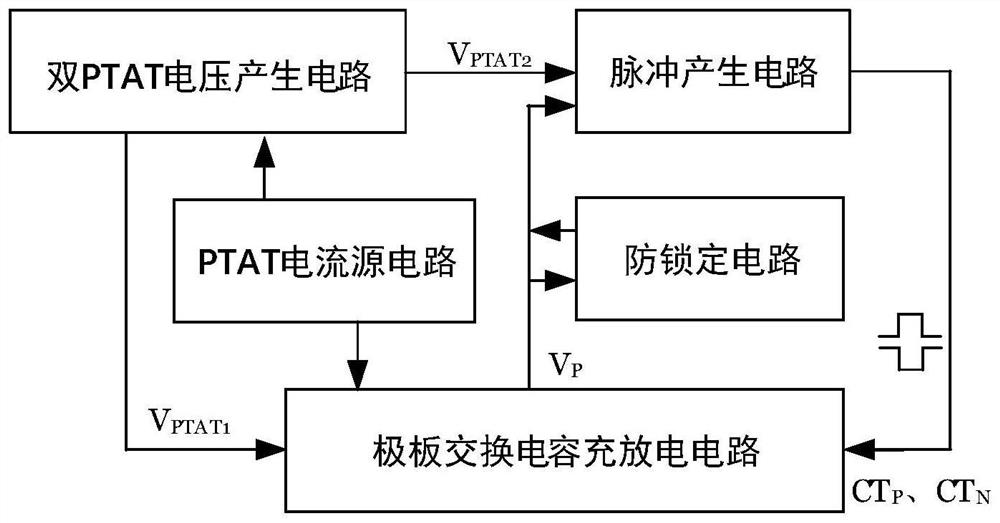
[0025] An embodiment of the present invention provides a resistanceless relaxation oscillator based on capacitive plate exchange, including a PTAT current source circuit 10 , a dual PTAT voltage generating circuit 20 , a plate exchange capacitor charging and discharging circuit 30 and a pulse generating circuit 40 .

[0026] The output end of described PTAT current source circuit 10 is respectively connected with the input end of described double PTAT voltage genera...


PUM


Abstract

The invention discloses a resistor-free relaxation oscillator based on capacitor plate exchange. The resistor-free relaxation oscillator comprises a PTAT current source circuit, a double PTAT voltage generation circuit, a plate exchange capacitor charging and discharging circuit and a pulse generation circuit, the output end of the PTAT current source circuit is connected with the input end of the double-PTAT voltage generation circuit and the first input end of the polar plate exchange capacitor charging and discharging circuit. The first output end of the double-PTAT voltage generation circuit is connected with the second input end of the polar plate exchange capacitor charging and discharging circuit, and the second output end of the double-PTAT voltage generation circuit is connected with the first controlled end of the pulse generation circuit; and a first controlled end and a second controlled end of the polar plate exchange capacitor charging and discharging circuit are respectively connected with a first control end and a second control end of the pulse generation circuit. By adopting the embodiment of the invention, the relaxation oscillator is realized under a resistor-free capacitor plate exchange circuit structure, and the production cost is saved while the low delay is ensured.

Description

technical field [0001] The invention relates to the field of integrated circuit design, in particular to a non-resistance relaxation oscillator based on capacitive plate exchange. Background technique [0002] In a system on chip, the system clock source of the digital circuit is usually a crystal oscillator, a fully on-chip ring oscillator or a fully on-chip relaxation oscillator. Crystal oscillators are often used in systems with wireless communication or high-speed interfaces, and their frequency stability is high, while their power consumption and cost are high; ring oscillators are usually used in high-frequency digital systems, their resonance frequency is high, but the frequency Poor stability and high power consumption; relaxation oscillators are usually used in low-frequency digital systems. Although their frequency stability is low, they have low power consumption, simple structure, high frequency-temperature stability, and low cost. Advantages, especially for ult...

Claims


Application Information

Patent Timeline
IPC IPC(8): H03K3/0231H03K3/012
CPCH03K3/0231H03K3/012Y02D30/70
Inventor 徐华超胡胜发
Owner ANYKA (GUANGZHOU) MICROELECTRONICS TECH CO LTD
Features
  • Generate Ideas
  • Intellectual Property
  • Life Sciences
  • Materials
  • Tech Scout
  • Unparalleled Data Quality
  • Higher Quality Content
  • 60% Fewer Hallucinations
Learn More